Periodic leaky-wave antenna with highly stable gain based on composite left-right hand structure

A technology of composite left-handed and leaky-wave antennas, which is applied in the direction of leaky waveguide antennas, antennas, antenna grounding devices, etc., can solve the problems that the main beam gain cannot be guaranteed stable and the gain variation range is large, and the gain amplitude fluctuation is not obvious, and the scanning range Large, guaranteed high stability effect

Active Publication Date: 2020-12-08
NANCHANG UNIV
View PDF10 Cites 3 Cited by
  • Summary
  • Abstract
  • Description
  • Claims
  • Application Information

AI Technical Summary

Problems solved by technology

[0004]In addition, most periodic leaky-wave antennas at this stage cannot guarantee the stability of the main beam gain under the premise of eliminating the open-stop band, and the gain variation is too large, which is harmful to the antenna Performance and application bring certain disadvantages

Method used


Image

  • Periodic leaky-wave antenna with highly stable gain based on composite left-right hand structure
  • Periodic leaky-wave antenna with highly stable gain based on composite left-right hand structure
  • Periodic leaky-wave antenna with highly stable gain based on composite left-right hand structure

Examples


Embodiment Construction

[0033] Below in conjunction with accompanying drawing, the present invention will be further described.

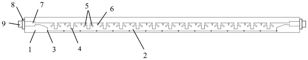
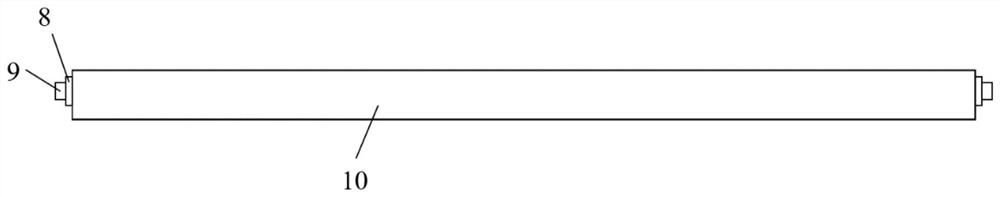
[0034] Such as figure 1 and figure 2 The structural diagram shown is a periodic leaky-wave antenna with highly stable gain based on a composite left-handed structure, including a dielectric plate 1, a metal transmission belt 2, a metal floor 10, and two sets of feed connectors, wherein the metal transmission belt 2 is located on the dielectric plate The upper surface of 1 and the metal floor 10 are located on the lower surface of the dielectric board 1, and two sets of feeder connectors are respectively located on the front and rear sides of the dielectric board 1.

[0035] Specifically, the medium plate 1 is a cuboid with a solid medium inside. This embodiment has used the dielectric plate material of Rogers 5880, and its relative permittivity ε r =2.2, dielectric loss tangent tanδ=0.0009. The metal floor 10 and the metal transmission belt 2 are planar structures, an...


PUM


Abstract

The invention discloses a periodic leaky-wave antenna with highly stable gain based on a composite left-right hand structure. The antenna comprises a dielectric plate, a metal transmission band, a metal floor, a feed connector and an impedance matching unit, and the metal transmission band is formed by cascading a plurality of composite left-right hand units which are periodically arranged on a microstrip transmission line; wherein each composite left-right hand unit comprises a metal connecting body, transverse straight grooves, inclined grooves and additional small grooves, a plurality of groups of transverse straight grooves are etched on one side of a metal conveying belt along the length direction, a plurality of metal connecting bodies are arranged on the other side of the metal conveying belt, the additional small grooves are etched between every two adjacent transverse straight grooves, and the inclined grooves are etched on two sides of each group of transverse straight grooves. According to the invention, the open stopband effect of the traditional periodic leaky-wave antenna is eliminated, the attenuation-free scanning in the edge emission direction can be realized, thebeam scanning range is large in the working range, the directivity is strong, the beam gain maintains high stability, and the leaky-wave antenna can be widely applied to the fields of multipoint communication, automobile radar and the like.

Description

technical field [0001] The invention belongs to the field of wireless communication applications, and in particular relates to a periodic leaky wave antenna with highly stable gain based on a composite left and right hand structure. Background technique [0002] Leaky wave antennas are a type of antennas that use traveling waves as the main radiation mechanism in a guided wave structure. A leaky wave is essentially a radiated wave. When the wave propagates in the waveguide structure, it will continuously radiate or leak energy, hence the name of the leaky wave antenna. A major advantage of leaky wave antennas is their inherent frequency scanning capability, which is suitable for multipoint communications, automotive radars, and high-resolution radars used in missile terminal guidance, etc., so they are widely used. [0003] According to structural classification, leaky wave antennas can be divided into three categories: uniform leaky wave antennas, quasi-uniform leaky wave...

Claims


Application Information

Patent Timeline
Patent Type & Authority Applications(China)
IPC IPC(8): H01Q13/20H01Q1/38H01Q1/50H01Q1/48H01Q5/335H01Q5/28
CPCH01Q13/206H01Q1/38H01Q1/50H01Q1/48H01Q5/335H01Q5/28Y02D30/70
Inventor 张超群张明渝陈良兵周松
Owner NANCHANG UNIV
Why Eureka
Try Eureka