Upper and lower clamping hanger for electroplated PCB

A PCB board and backplane technology, which is applied in the field of upper and lower clamping fixtures on electroplating PCB boards, can solve the problems of no copper in holes, and the PCB board cannot be completely penetrated by liquid medicine, and achieves low cost loss rate, simple structure, and expanded application scope. Effect

Pending Publication Date: 2020-12-11
吉希易机械设备(东莞)有限公司
0 Cites 0 Cited by

AI-Extracted Technical Summary

Problems solved by technology

[0003] At present, the PCB board itself is too thin during the electroplating process, and it will wrinkle and bend, so that the small aperture on the PCB board cannot be completely penetrated by the potion, and it is easy to cause holes without copper. It is...

Abstract

The invention discloses an upper and lower clamping hanger for a PCB. The upper and lower clamping hanger comprises a connector; an adjusting back plate is mounted on the connector; a first sliding block and a second sliding block are mounted on the adjusting back plate; a first through hole is formed in the first sliding block; a second through hole is formed in the second sliding block; a firstsupporting rod is movably mounted in the first through hole; the first sliding block linearly moves up and down along the first supporting rod in a reciprocating mode; the second through hole is movably provided with a second supporting rod; the second sliding block linearly moves up and down along the second supporting rod in a reciprocating mode; the adjusting back plate is provided with a plurality of upper electroplating clamps used for clamping the upper portion of a PCB; the lower ends of the first supporting rod and the second supporting rod are provided with a fixed back plate; and thefixed back plate is provided with a plurality of lower electroplating clamps used for clamping the lower portion of the PCB. The upper and lower clamping hanger is high in production efficiency, lowin cost loss rate, capable of achieving automatic continuous batch production, high in yield, long in service life and free of frequent replacement.

Application Domain

Electrolysis components

Technology Topic

Batch productionStructural engineering +2

Image

  • Upper and lower clamping hanger for electroplated PCB
  • Upper and lower clamping hanger for electroplated PCB
  • Upper and lower clamping hanger for electroplated PCB

Examples

  • Experimental program(1)

Example Embodiment

[0025] The technical solutions in this embodiment of the present invention will be clearly and completely described below in conjunction with the accompanying drawings in this embodiment of the present invention. Obviously, the described embodiment is an embodiment of the present invention, not all This embodiment. Based on this implementation manner in the present invention, all other implementation manners obtained by persons of ordinary skill in the art without making creative efforts fall within the protection scope of the present invention.
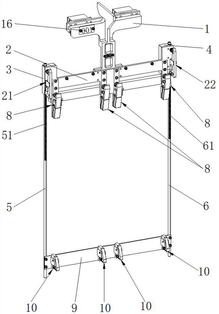
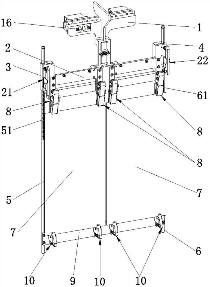
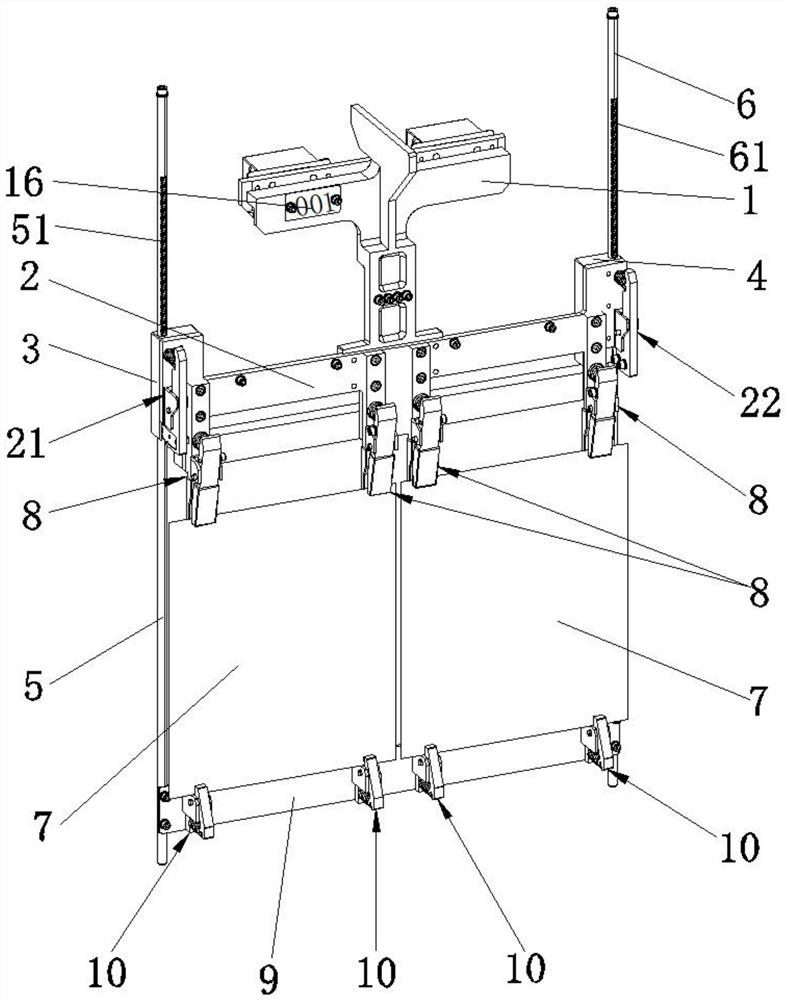
[0026] Please refer to Figure 1 to Figure 6 , the present invention provides an electroplating PCB board upper and lower clamping hanger, including a connector 1, the connector 1 is connected to an automated assembly line to realize automatic movement of the hanger, automatic production and mass production, and high production efficiency , The cost loss rate is low, and the yield rate of the product is improved.
[0027] The connector 1 is provided with an adjustment backplane 2, one side of the adjustment backplane 2 is equipped with a first sliding block 3, and the other side is equipped with a second sliding block 4, and the first sliding block 3 and The second sliding block 4 is fixed on the adjustment back plate 2, and the adjustment back plate 2 moves together with the first sliding block 3 and the second sliding block 4, and the first sliding block 3 is provided with a first through hole 31 , the second sliding block 4 is provided with a second through hole 41, the first through hole 31 is movably equipped with a first support rod 5, and the first sliding block 3 reciprocates up and down along the first support rod 5 Linear movement, the second through hole 41 is movably equipped with a second support rod 6, the second sliding block 4 reciprocates linearly up and down along the second support rod 6, and the adjustment back plate 2 can move along the first The support rod 5 and the second support rod 6 reciprocate linearly up and down, and the distance between the backboard 2 and the fixed backboard 9 can be adjusted to adapt to PCB boards 7 of different sizes and expand the scope of application of the hanger.
[0028] The adjustment backplane 2 is equipped with several upper electroplating clamps 8 for clamping the upper part of the PCB board 7, and the lower ends of the first support rod 5 and the second support rod 6 are equipped with a fixed backplane 9, and the fixed The back plate 9 is equipped with several lower plating clips 10 for clamping the lower part of the PCB board 7, the upper and lower ends of the PCB board 7 are fixed on the hanger by the plating clips, the structure is simple, the operation is safe and reliable, and the operation is simple and convenient , The hanger has a long service life and does not need to be replaced frequently.
[0029] The surface of the first support rod 5 is provided with a first scale groove 51, the surface of the second support rod 6 is provided with a second scale groove 61, and the first scale groove 51 and the second scale groove are installed. The slot 61 can quickly adjust the distance between the backplane 2 and the fixed backplane 9 , save operation time, improve operation efficiency, and adapt to PCB boards 7 of different sizes.
[0030] One side of the adjustment backboard 2 is equipped with a first thrust assembly 21, and the other side is equipped with a second thrust assembly 22, and the first thrust assembly 21 is used in conjunction with the first sliding block 3. The second thrust assembly 22 is used in cooperation with the second sliding block 4 , the first thrust assembly 21 includes a first installation support 211 , and the first installation support 211 is connected to the first thrust member through a first pin 212 213, one end of the first thrust member 213 is equipped with a first spring 214, and the other end is clamped on the first scale groove 51, and the second thrust assembly 22 includes a second mounting support 221, so The second mounting support 221 is connected to the second thrust member 223 through the second pin 222 , the second thrust member 223 is provided with a second spring 224 at one end, and the other end is engaged with the second scale groove 61 .
[0031] Quickly adjust and adjust the distance between the back plate 2 and the fixed back plate 9, compress the first spring 214 and the second spring 224, so that the first thrust member 213 is separated from the first scale groove 51, and the second thrust member 223 is separated from the first scale groove 51. The second scale groove 61 is separated, and the first sliding block 3 and the second sliding block 4 can reciprocate linearly up and down along the first support bar 5 and the second support bar 6, so that the adjustment back plate 2 can move along the first The support bar 5 and the second support bar 6 reciprocate linearly up and down, the distance between the adjustment back plate 2 and the fixed back plate 9 changes, and the adjustment back plate 2 is moved to a suitable position according to actual production needs, and the first spring is relaxed 214 and the second spring 224, so that the first thrust piece 213 is stuck with the first scale groove 51, the second thrust piece 223 is stuck with the second scale groove 61, and the position of the adjustment backboard 2 is fixed at On the first support rod 5 and the second support rod 6 .
[0032] The upper electroplating clamp 8 includes a first mounting block 81, which is fixedly mounted on the adjustment backplane 2, and a third mounting support 82 is mounted on the first mounting block 81, and the first mounting block 81 is equipped with a third mounting support 82. The third installation support 82 is installed in the middle of the first installation block 81, the third installation support 82 is connected to the first jaw 84 through the third pin 83, and a third spring is installed at one end of the first jaw 84. 85, one end of the third spring 85 is installed on the first mounting block 81, and the other end is connected to the first jaw 84, and one end of the first mounting block 81 and the first jaw 84 are equipped with an electroplating clamping point 86 , the electroplating clip pinch point 86 is electrically connected to the PCB board 7 , and one end of the first mounting block 81 and the first jaw 84 is provided with a first insulating sleeve 87 except the electroplating clip pinch point 86 .
[0033] The process of the upper electroplating clamp 8 loosening and clamping the PCB board 7: compressing the third spring 85 makes the distance between the first mounting block 81 and the first jaw 84 increase, and the PCB board 7 can be lifted from the first mounting block 81 and the first jaw 84, loosen the third spring 85 so that the distance between the first mounting block 81 and the first jaw 84 is reduced, and the PCB board 7 can be placed between the first mounting block 81 and the first clamping Clamping is performed between the jaws 84 .
[0034] The lower electroplating clamp 10 includes a fourth mounting support 11, the fourth mounting support 11 is fixedly installed on the fixed backplane 9, and the second mounting block 12 is installed on the fourth mounting support 11, so that The fourth mounting support 11 is connected to the second jaw 14 through the fourth pin 13, and a fourth spring 15 is installed at one end of the second jaw 14, and the second mounting block 12 and the second jaw 14 are used together .
[0035] The process of the lower electroplating clip 10 loosening and clamping the PCB board 7: compressing the fourth spring 15 makes the distance between the second mounting block 12 and the second jaw 14 increase, and the PCB board 7 can be lifted from the second mounting block 12 and the second jaw 14, loosen the fourth spring 15 so that the distance between the second mounting block 12 and the second jaw 14 is reduced, and the PCB board 7 can be placed between the second mounting block 12 and the second clamping Clamping takes place between the jaws 14.
[0036] The connecting head 1 is equipped with an identifiable marking symbol 16, which is used to identify the serial number, specification model, usage or other information of the hanging device.
[0037] In this embodiment, four of the upper electroplating clamps 8 and the lower electroplating clamps 10 are installed, and two PCB boards 7 are installed between the first support rod 5 and the second support rod 6, and the The distance between the first support rod 5 and the second support rod 6 is 500mm, the distance between the adjustment backboard 2 and the fixed backboard 9 can be adjusted between 300-500mm, and in other embodiments the above data can be Adjust according to actual production needs.
[0038] In the process of using the upper and lower clamping hangers on the electroplated PCB board, firstly, connect the connector 1 to the automatic assembly line; secondly, adjust the distance between the backplane 2 and the fixed backplane 9; finally, install the PCB board 7 It is arranged between the upper electroplating clamp 8 and the lower electroplating clamp 10 to automatically process the PCB board 7 .
[0039] In summary, the beneficial effects of the present invention are:
[0040] The present invention is equipped with an upper electroplating clip 8 and a lower electroplating clip 10, which can fix the PCB board 7 on the hanger, has a simple structure, safe and reliable operation, simple and convenient operation, a long service life of the hanger, and does not need frequent replacement; the present invention The first sliding block 3 can move up and down linearly along the first support bar 5, and the second sliding block 4 can move up and down linearly along the second support bar 6, and can adjust the gap between the back plate 2 and the fixed back plate 9 distance, to adapt to PCB boards 7 of different sizes, and expand the scope of application of the hanger; the hanger of the present invention can be connected on the assembly line to realize automatic production and mass production, with high production efficiency, low cost loss rate, and improved yield of products .

PUM

no PUM

Description & Claims & Application Information

We can also present the details of the Description, Claims and Application information to help users get a comprehensive understanding of the technical details of the patent, such as background art, summary of invention, brief description of drawings, description of embodiments, and other original content. On the other hand, users can also determine the specific scope of protection of the technology through the list of claims; as well as understand the changes in the life cycle of the technology with the presentation of the patent timeline. Login to view more.

Similar technology patents

Body condition measuring device

InactiveUS20050234351A1simple structure
Owner:DENSO CORP

Magnetic cooling apparatus and control method thereof

ActiveUS20130180263A1simple structure
Owner:SAMSUNG ELECTRONICS CO LTD

Dual-Drivetrain of Power-Assist Vehicle

InactiveUS20100181130A1enhance uphill momentumsimple structure
Owner:CHOU WEN CHENG

Classification and recommendation of technical efficacy words

  • Simple structure
  • operational security

Sharing system for air-conditioning coat

InactiveCN107440179ASimple structureeasy to wear
Owner:QINGDAO HAIER AIR CONDITIONER GENERAL CORP LTD

Feeding device of sorter of batteries plate

InactiveCN101357717ASimple structurecooperate well
Owner:NANJING NORMAL UNIVERSITY

Emergency parachuting device and method for multiple-rotor unmanned aerial vehicle

InactiveCN103895870Aavoid aircraft crashSimple structure
Owner:SOUTH CHINA AGRI UNIV +1

Numerically-controlled milking composite machine tool

InactiveCN101508069ASmall temperature rise and thermal deformationoperational security
Owner:CHANGSHA JINLING MACHINE TOOL

Synthetic process of SAPO-11 Molecular sieve

InactiveCN1834015AProcess economy is strongoperational security
Owner:PETROCHINA CO LTD +1

Automatic stripper for scrap cable

InactiveCN104821521Aoperational securityQuick Strip
Owner:STATE GRID CORP OF CHINA +1

Battery

Owner:POSITEC POWER TOOLS (SUZHOU) CO LTD +1
Why Eureka
Try Eureka