Cavity filtering antenna with high gain, high selectivity and low loss

A high-selectivity, cavity filtering technology, applied in the field of communication antennas, can solve the problems of low gain, large antenna volume, and poor radiation characteristics, and achieve the effects of low processing cost, high filtering performance, and high gain performance

Inactive Publication Date: 2020-12-11
SOUTH CHINA UNIV OF TECH
View PDF7 Cites 6 Cited by
  • Summary
  • Abstract
  • Description
  • Claims
  • Application Information

AI Technical Summary

Problems solved by technology

In the prior art, some use a three-mode resonant cavity to design a three-frequency filter cavity antenna, and some use a cavity and an antenna to comprehensively design a cavity filter antenna array with centimeter and filter functions, but these designs generally have radiation characteristics Not good and the gain is not high, and the design of the multi-stage cavity will make the volume of the antenna larger

Method used


Image

  • Cavity filtering antenna with high gain, high selectivity and low loss
  • Cavity filtering antenna with high gain, high selectivity and low loss
  • Cavity filtering antenna with high gain, high selectivity and low loss

Examples


Embodiment Construction

[0024] The present invention will be further described below in conjunction with specific examples.

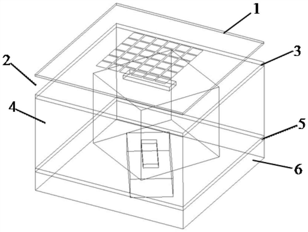
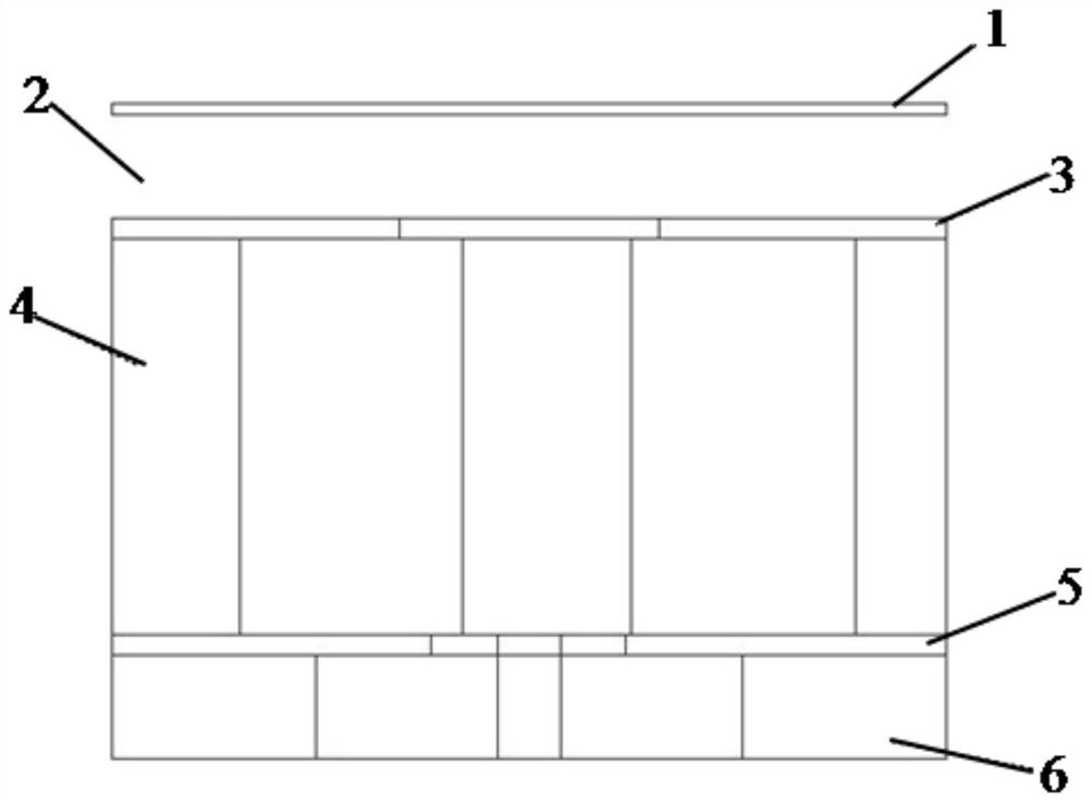
[0025] see Figure 1 to Figure 7 As shown, this embodiment provides a cavity filter antenna with high gain, high selectivity and low loss, including a dielectric plate 1, a first metal block 3, a second metal block 4, and a third metal plate arranged in sequence from top to bottom. Block 5, the fourth metal block 6, the distance between the dielectric plate 1 and the first metal block 3 is kept 5mm, an air layer 2 is formed, the first metal block 3, the second metal block 4, the third metal block Both the block 5 and the fourth metal block 6 are cuboid metal blocks;

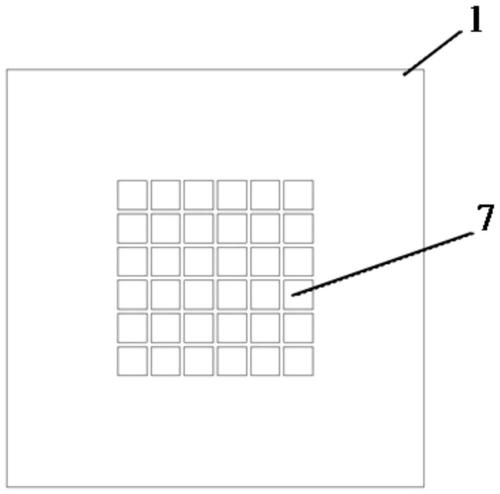
[0026] Wherein, the grid slotted patch 7 is provided on the dielectric board 1, and the grid slotted patch 7 is a 6×6 square patch for improving the gain of the antenna; the first metal block 3 The thickness is 1 mm, and the middle part of the first metal block 3 has a radiation hole 8, which is a rectangular h...


PUM

PropertyMeasurementUnit
thicknessaaaaaaaaaa
thicknessaaaaaaaaaa
thicknessaaaaaaaaaa

Abstract

The invention discloses a cavity filtering antenna with high gain, high selectivity and low loss. The cavity filtering antenna comprises a dielectric plate, a first metal block, a second metal block,a third metal block and a fourth metal block, a preset distance is kept between the dielectric plate and the first metal block to form an air layer, the fourth metal block is provided with a waveguideexcitation port used for inputting energy, the second metal block is provided with a three-mode resonant cavity, the third metal block is provided with a coupling hole used for coupling the energy ofthe waveguide excitation port to the three-mode resonant cavity, and the first metal block is provided with a radiation hole used for radiating energy. The dielectric plate is provided with a grid slotted patch for improving the gain of the antenna. According to the invention, within the frequency range of 9.8 GHz to 10.2 GHz, the return loss is not larger than -11 dB, meanwhile, the gain is keptat 10 dBi, a transmission zero point is generated at the 9.76 GHz frequency point and the 10.4 GHz frequency point, the low-loss, high-gain and high-selectivity filtering performance is achieved, andmeanwhile the characteristics of being simple in design, low in machining cost and low in loss are achieved.

Description

technical field [0001] The invention relates to the technical field of communication antennas, in particular to a cavity filter antenna with high gain, high selectivity and low loss. Background technique [0002] With the rapid development of wireless communication systems, the requirements for communication equipment are getting higher and higher. Antennas are important devices in communication systems, and integrating more functions into them is a research hotspot. Due to the low unloaded quality factor of the microstrip resonator, a certain loss will occur when it is used to realize the filter antenna, and the cavity resonator has a loss compared with the microstrip resonator due to the high unloaded quality factor. Therefore, designing a filter antenna with high selectivity, high gain and low loss has great application value. In the prior art, some use a three-mode resonant cavity to design a three-frequency filter cavity antenna, and some use a cavity and an antenna to...

Claims


Application Information

Patent Timeline
Patent Type & Authority Applications(China)
IPC IPC(8): H01Q9/04H01Q1/00H01Q1/24
CPCH01Q1/002H01Q1/241H01Q9/0407
Inventor 陈付昌向凯燃
Owner SOUTH CHINA UNIV OF TECH
Why Eureka
Try Eureka