
Drilling device for machining fan shell

A technology of drilling device and casing, applied in positioning device, boring/drilling, metal processing equipment, etc., can solve the problems of reducing drilling efficiency and unsatisfactory drilling effect, etc.

Inactive Publication Date: 2020-12-22
江西艾斯欧匹精密智造科技有限公司
View PDF6 Cites 2 Cited by
  • Summary
  • Abstract
  • Description
  • Claims
  • Application Information

AI Technical Summary

Problems solved by technology

[0003] The unpowered ventilator uses the natural wind force and the air heat convection caused by the temperature difference between indoor and outdoor to drive the turbine to rotate so as to use the centrifugal force and negative pressure effect to discharge the indoor stale hot air. The fan is related to the transmission and distribution energy consumption of the system. Energy saving is a very critical part. According to the inspection of fans by the National Air Conditioning Equipment Quality Supervision and Inspection Center for many years, many fans have problems under rated working conditions. Therefore, fans need to be produced and manufactured in strict accordance with product standards. The main structural components of fans are impellers, casings , air inlets, brackets, motors, pulleys, couplings, mufflers, transmission parts (bearings), etc., drilling devices are required in the process of processing the fan casing, but the existing drilling devices have a good drilling effect It is not ideal, thus reducing the drilling efficiency. Therefore, we propose a drilling device for fan casing processing

Method used


Image

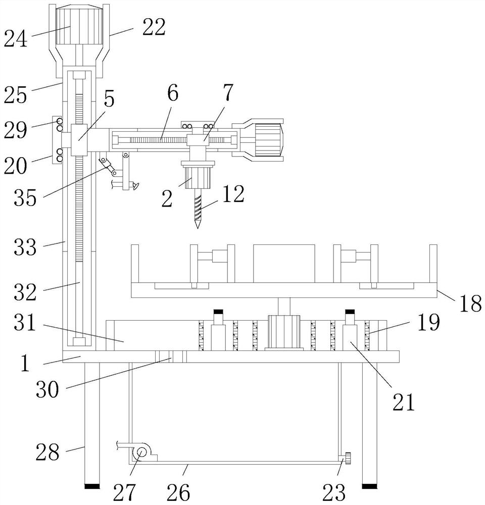
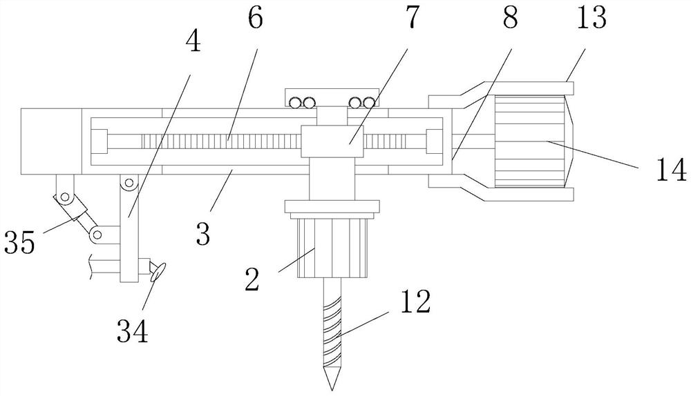
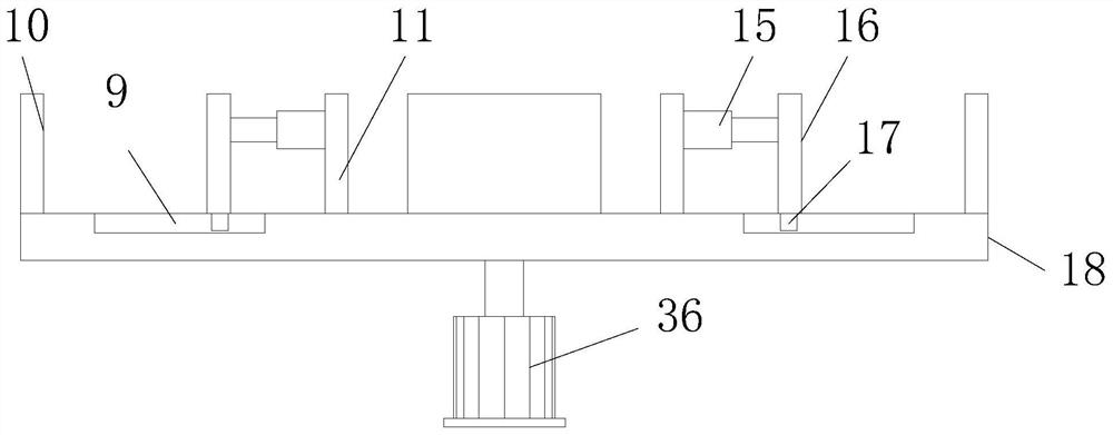
  • Drilling device for machining fan shell
  • Drilling device for machining fan shell
  • Drilling device for machining fan shell

Examples


Embodiment Construction

[0018] The following will clearly and completely describe the technical solutions in the embodiments of the present invention with reference to the accompanying drawings in the embodiments of the present invention. Obviously, the described embodiments are only some, not all, embodiments of the present invention. Based on the embodiments of the present invention, all other embodiments obtained by persons of ordinary skill in the art without making creative efforts belong to the protection scope of the present invention.

[0019] In the description of this application, it should be noted that, unless otherwise clearly specified and limited, the terms "installed", "set with", "connected", etc. should be understood in a broad sense, such as "connected", which can be a fixed connection , can also be detachably connected, or integrally connected; can be mechanically connected, can also be electrically connected; can be directly connected, can also be indirectly connected through an i...


PUM


Abstract

The invention discloses a drilling device for machining a fan shell. The drilling device comprises a workbench and a first electric telescopic rod; a water storage tank is fixedly connected to the middle end of the bottom of the workbench; and a pump with the output end communicating with a spray head through a pipeline is fixedly installed at the left end of the bottom of an inner cavity of the water storage tank. The drilling device is provided with a first support, a first motor bracket, a first motor, a first conveying shaft and a first threaded sleeve, so that the vertical position of a drill rod can be adjusted; a second support, a second motor bracket, a second motor, a second conveying shaft and a second threaded sleeve are arranged, so that the horizontal position of the drill rodcan be adjusted; a third motor and the drill rod are arranged, so that the purpose of drilling the fan shell is realized; a fourth motor, a clamping platform, a fixed clamping plate, a supporting plate, a third electric telescopic rod and a movable clamping plate, so that the purpose of continuous drilling operation can be achieved; and the water storage tank, the pump, the pipeline and the sprayhead are arranged, so that the purpose of dust falling of dust can be achieved.

Description

technical field [0001] The invention relates to the technical field of fans, in particular to a drilling device for processing fan casings. Background technique [0002] The fan is a machine that relies on the input mechanical energy to increase the gas pressure and discharge the gas. It is a driven fluid machine. It is the abbreviation of China's habit of gas compression and gas delivery machinery. Usually, the so-called fan includes ventilator, blower, Wind generators and fans are widely used in ventilation, dust removal and cooling of factories, mines, tunnels, cooling towers, vehicles, ships and buildings, ventilation and induction of boilers and industrial furnaces, air conditioning equipment and household appliances Cooling and ventilation, grain drying and selection, wind tunnel wind source and hovercraft inflation and propulsion, etc. [0003] The unpowered ventilator uses the natural wind force and the air heat convection caused by the temperature difference betwee...

Claims


Application Information

Patent Timeline
IPC IPC(8): B23B41/00B23Q3/06B23Q1/25B23Q11/00
CPCB23B41/00B23Q1/25B23Q3/062B23Q11/0042
Inventor 张富强
Owner 江西艾斯欧匹精密智造科技有限公司
Learn More