High-temperature mechanical simulation and in-situ observation device
A high-temperature mechanics and observation device technology, which is applied to measuring devices, scientific instruments, instruments, etc., can solve problems such as difficult in-situ observation and slow heating speed
- Summary
- Abstract
- Description
- Claims
- Application Information
AI Technical Summary
Problems solved by technology
Method used
Image

Examples
Embodiment 1
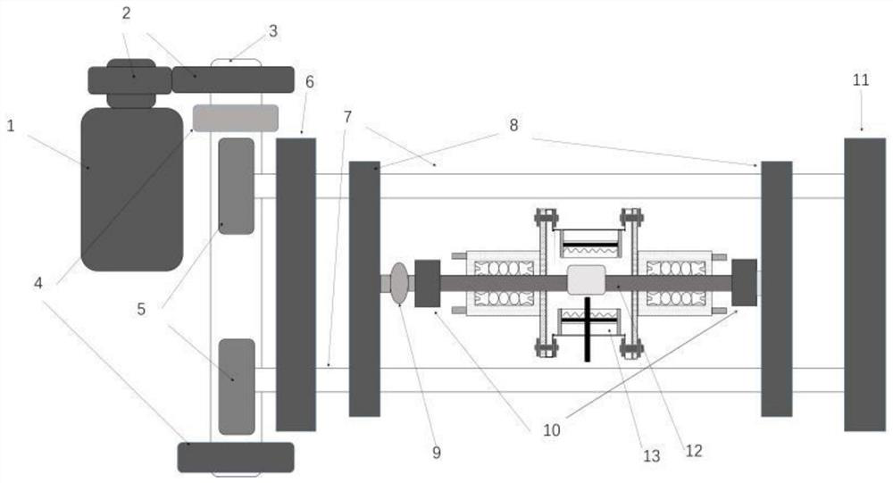
[0035] Such as figure 1 As shown, a high-temperature mechanical simulation and in-situ observation device includes a motor 1, a gear 2, a worm 3, a bearing support seat 4, a turbine 5, a transmission seat 6, a left and right screw rod 7, a nut seat 8, and a stress sensor 9 , clamp 10, screw support seat 11, sample 12, high temperature environment box 13; wherein the worm 3 and the bearing support seat 4 are connected by bearings, and the worm 3 and the turbine 5 are engaged to form a reduction mechanism; the left and right screw rods 7 and the transmission seat 6 and the screw support seat 11 are connected by bearings; the fixture 10 on the left is connected to the nut seat 8 on the left through a stress sensor 9; the motor 1 is used to control the magnitude and frequency of stress; the high temperature environment box 13 is used to simulate a high temperature environment.
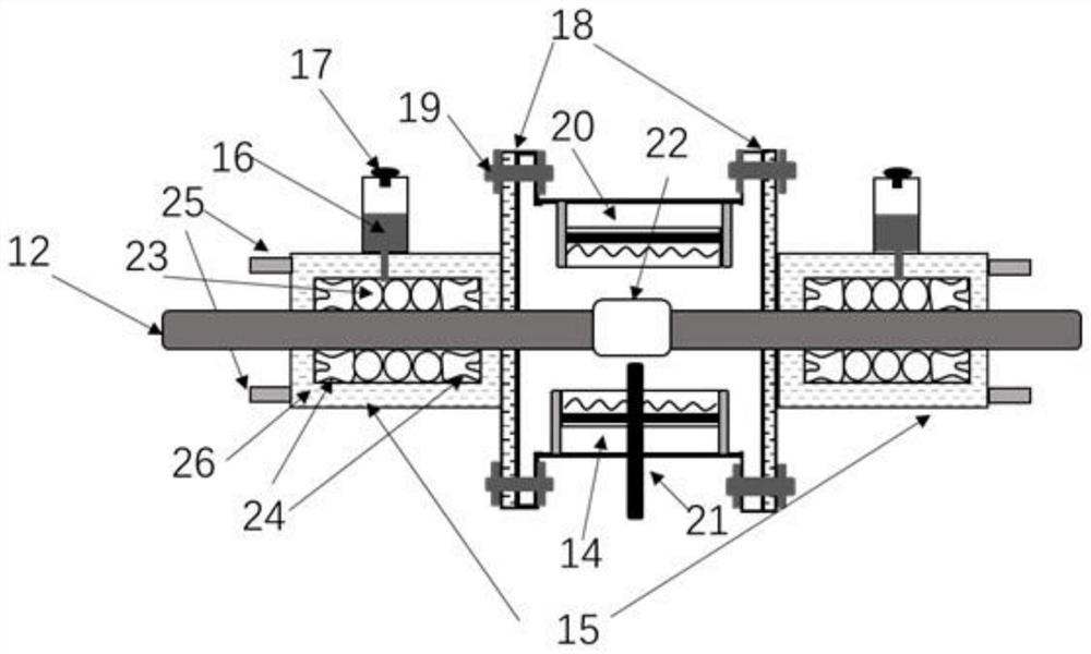
[0036] Such as figure 2 As shown, the high temperature environment chamber 13 includes a main body te...
Embodiment 2
[0057] The difference between this embodiment and embodiment 1 is that the material of the test piece 12 is a low carbon steel bar, its length is 100 mm, and its diameter is 3 mm. 18 is made of 1Cr18Ni9Ti stainless steel wire with a diameter of 0.15mm. The diameter of the magnetic ball 23 is 200μm. The surface of the magnetic ball 23 is coated with barium strontium niobate piezoelectric coating. The inner diameter of the Y-shaped high-temperature resistant rubber sealing ring is 3.3mm. Y-type high temperature resistant rubber sealing ring is a double fluorine rubber ring containing nano-magnesia. The surface of nano-magnesia is modified by magnesium stearate and maleic anhydride. Magnesium stearate 10 times the amount of nano-magnesium oxide mixed and added to the beaker, poured into an appropriate amount of ethyl acetate to obtain a mixed solution, the addition of ethyl acetate is equivalent to 20 times the amount of magnesium stearate weight; Stir in a magnetic stirrer at 90...
Embodiment 3
[0059] The difference between this embodiment and embodiment 1 is that the material of the test piece 12 is an aluminum alloy rod, its length is 80mm, and its diameter is 4mm. Made of 0Cr18Ni9Ti stainless steel wire and 1Cr18Ni9Ti stainless steel wire, the diameters are 0.08mm and 0.12mm respectively, the diameter of the magnetic ball 23 is 100μm, the surface of the magnetic ball 23 is covered with barium titanate piezoelectric coating, and the Y-shaped high temperature resistant rubber is selected The inner diameter of the sealing ring is 4.1mm. The Y-type high-temperature-resistant rubber sealing ring is a bifluororubber ring containing nano-alumina. The surface of the nano-alumina is modified by magnesium stearate and maleic anhydride. The modification process is: first Magnesium stearate is mixed with nano-alumina equivalent to 13 times the amount of magnesium stearate and added to a beaker, and an appropriate amount of ethyl acetate is poured into it to obtain a mixed solu...
PUM
| Property | Measurement | Unit |
|---|---|---|
| diameter | aaaaa | aaaaa |
| angle | aaaaa | aaaaa |
| length | aaaaa | aaaaa |
Abstract
Description
Claims
Application Information
 - R&D
- Intellectual Property
- Life Sciences
- Materials
- Tech Scout
- Unparalleled Data Quality
- Higher Quality Content
- 60% Fewer Hallucinations
Browse by: Latest US Patents, China's latest patents, Technical Efficacy Thesaurus, Application Domain, Technology Topic, Popular Technical Reports.
© 2025 PatSnap. All rights reserved.Legal|Privacy policy|Modern Slavery Act Transparency Statement|Sitemap|About US| Contact US: help@patsnap.com