
Aluminum plate machining device

A processing device and aluminum sheet technology, which is applied in the direction of grinding drive device, metal processing equipment, grinding/polishing safety device, etc., can solve problems such as troublesome fixing and dismounting of aluminum sheet, impact on the health of staff, inconvenient use, etc., and achieve Easy to fix and disassemble, good fixing effect, and the effect of reducing work intensity

Inactive Publication Date: 2020-12-25
TIANCHANG JINGFA ALUMINUM IND
View PDF10 Cites 5 Cited by
  • Summary
  • Abstract
  • Description
  • Claims
  • Application Information

AI Technical Summary

Problems solved by technology

[0003] Aluminum sheet is one of the types of aluminum materials. It refers to the use of plastic processing methods to manufacture aluminum billets into sheet-shaped aluminum products through rolling, extrusion, stretching and forging. In order to ensure the final performance of the sheet Finished products undergo annealing, solution treatment, quenching, natural aging and artificial aging treatment, and then during the processing of aluminum plates, aluminum plates are often polished to remove burrs on aluminum plates. Existing aluminum plate processing and grinding The fixing of the aluminum sheet by the device is generally clamping or pressing. Although it can achieve a good fixing effect, the fixing and disassembly of the aluminum sheet are very troublesome and inconvenient to use. At the same time, the aluminum sheet is being fixed. During the grinding process, more powder chips will be produced, which float in the air and will have a certain impact on the health of the staff

Method used


Image

  • Aluminum plate machining device
  • Aluminum plate machining device
  • Aluminum plate machining device

Examples


Embodiment Construction

[0030] The following will clearly and completely describe the technical solutions in the embodiments of the present invention with reference to the accompanying drawings in the embodiments of the present invention. Obviously, the described embodiments are only some, not all, embodiments of the present invention. Based on the embodiments of the present invention, all other embodiments obtained by persons of ordinary skill in the art without creative efforts fall within the protection scope of the present invention.

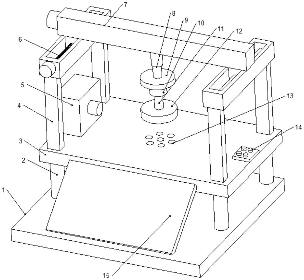
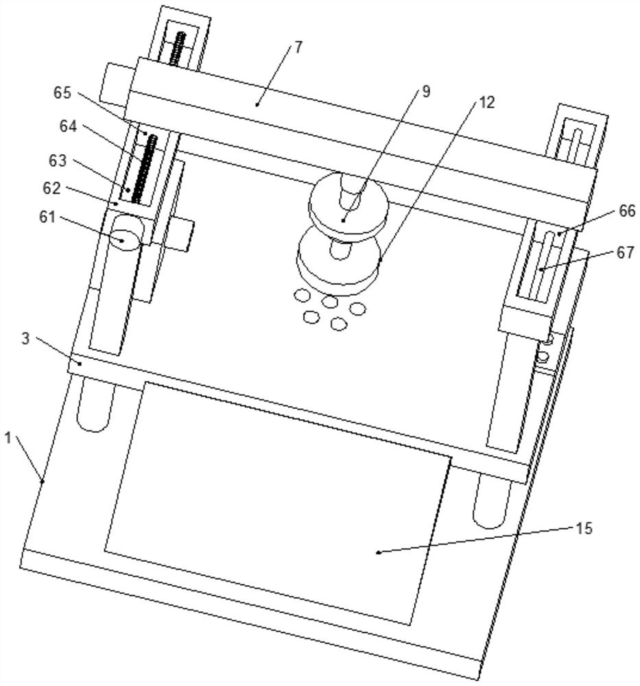
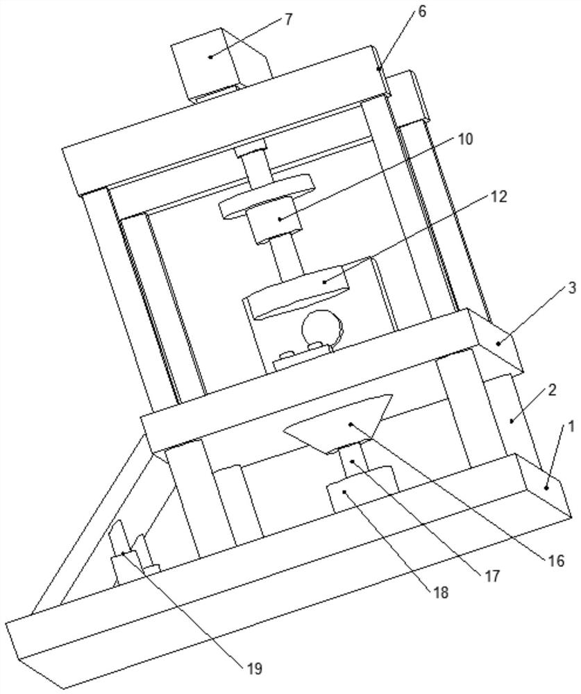
[0031] see Figure 1-5, the present invention provides a technical solution for an aluminum plate processing device: it includes a base 1 and a workbench 3, the base 1 and the workbench 3 are connected through support legs 2, and the four corners of the top of the workbench 3 are fixedly connected with A support rod 4, the top of the support rod 4 is connected with a longitudinal drive assembly 6, the longitudinal drive assembly 6 is connected with a transverse dri...


PUM


Abstract

The invention discloses an aluminum plate machining device. The aluminum plate machining device comprises a base and a workbench, wherein the base and the workbench are connected through supporting legs; the top of the workbench is connected with a supporting rod; the supporting rod is connected with a longitudinal drive assembly; the longitudinal drive assembly is connected with a transverse drive assembly; the bottom of the transverse drive assembly is connected with an electric telescopic rod; the electric telescopic rod is connected with a first motor through a connecting plate; the firstmotor is connected with a grinding disc through a rotation shaft; a dust collecting assembly is arranged on the left side of the top of the workbench; a plurality of sets of through holes are formed in the center position of the workbench; a vacuumizer is arranged on the top of the base and connected with an air pumping pipe, and the top end of the air pumping pipe is connected with an air pumpinghopper; the longitudinal drive assembly and the transverse drive assembly drive the grinding disc to rotate, and comprehensive grinding on an aluminum plate can be achieved; the aluminum plate is adsorbed and fixed to the workbench through the vacuumizer, and fixing and dismounting of the aluminum plate are very convenient; and powder generated during grinding is treated through the dust collecting assembly, and powder is prevented from floating in air.

Description

technical field [0001] The invention relates to the technical field of aluminum plate processing, in particular to an aluminum plate processing device. Background technique [0002] Aluminum (Al) is a light metal, and its compounds are widely distributed in nature. The resources of aluminum in the earth's crust are about 40 to 50 billion tons, second only to oxygen and silicon, and rank third. Among metal varieties, it is the second largest category of metals after steel. Aluminum has special chemical and physical properties. It is not only light in weight and strong in texture, but also has good ductility, electrical conductivity, thermal conductivity, heat resistance and nuclear radiation resistance. It is an important basic raw material for national economic development. Aluminum is an extremely abundant metal element on the earth, and its reserves rank second among metals. It was not until the end of the 19th century that aluminum emerged as a competitive metal in engi...

Claims


Application Information

Patent Timeline
Patent Type & Authority Applications(China)
IPC IPC(8): B24B9/04B24B41/02B24B41/00B24B41/06B24B47/12B24B55/06B01D46/00B01D46/12
CPCB24B9/04B24B41/02B24B41/005B24B41/068B24B47/12B24B55/06B01D46/12B01D46/0036B01D46/64
Inventor 林士兵朱良科
Owner TIANCHANG JINGFA ALUMINUM IND
Learn More