Device for preparing graphene crystal film through electron beam scanning
A technology of electron beam scanning and graphene, applied in crystal growth, post-processing equipment, single crystal growth, etc. Pollution of the surrounding environment and other issues, to meet the needs of large-scale batch production, meet the needs of laboratory scientific research work, and reduce the effect of discharge phenomena
- Summary
- Abstract
- Description
- Claims
- Application Information
AI Technical Summary
Problems solved by technology
Method used
Image
Examples
Embodiment 1
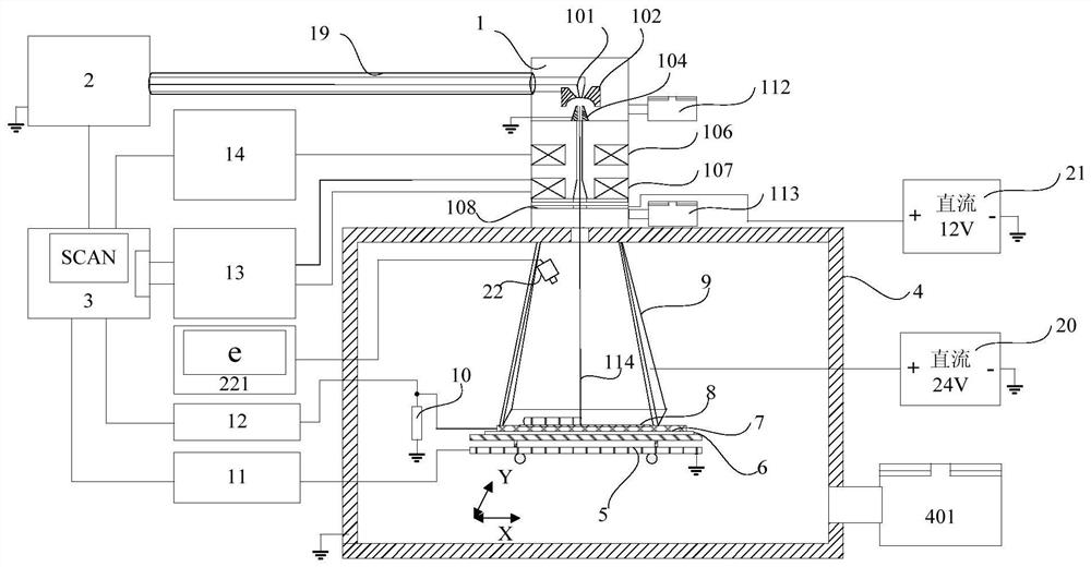
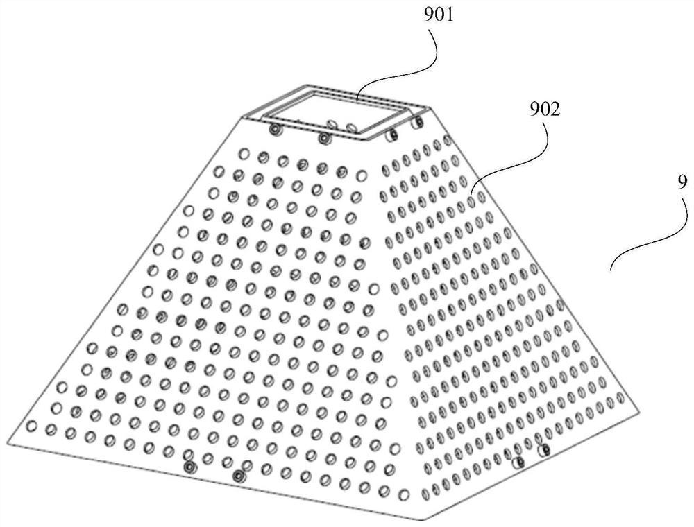
[0076] see figure 1 , the workbench is an X-Y workbench 5, and an infrared CCD system 22 is installed inside the toner adsorption cover 9, and the infrared CCD system 22 is electrically connected with a display 221 outside the vacuum chamber 4, and the infrared CCD The system 22 and the display 221 are used to observe the preparation state of the graphene crystal thin film, and adjust the graphene preparation work area so that the operator can observe the state of the work area.
[0077] In this embodiment, the detailed working process is as follows:
[0078] Step 1, open the X-Y workbench 5 to the outside of the vacuum chamber 4, lay the insulating plate 6 on the X-Y workbench 5, and then lay the metal substrate 7, connect the metal substrate 7 and the current sensor 10, and cover the metal substrate 7 with carbon polymer Thin film 8;
[0079] Step 2: Open the X-Y workbench 5 with the metal substrate 7 and the carbon polymer film 8 covered thereon into the vacuum chamber 4,...
Embodiment 2
[0094] see Image 6 , the workbench is an X workbench 17, the X workbench 17 is provided with a platform tooling 18, and the two sides of the platform tooling 18 are respectively equipped with a raw material installation rotating shaft 15 and a finished product installation rotating shaft 16;
[0095] The insulating plate 6 is installed on the platform tooling 18, one end of the carbon polymer film 8 is installed on the raw material installation shaft 15, and the other end is close to the metal substrate 7 and rolled by the finished product installation shaft 16. around.
[0096] In this embodiment, the detailed working process is as follows:
[0097] Step 1, open the X workbench 17 to the outside of the vacuum chamber 4, install the platform tooling 18 on the X workbench 17, place the metal substrate 7 on the platform tooling 18, and connect it with the current sensor 10; install the raw material on the rotating shaft 15, the finished product The installation shaft 16 is in...
PUM
| Property | Measurement | Unit |
|---|---|---|
| diameter | aaaaa | aaaaa |
Abstract
Description
Claims
Application Information
 - R&D
- Intellectual Property
- Life Sciences
- Materials
- Tech Scout
- Unparalleled Data Quality
- Higher Quality Content
- 60% Fewer Hallucinations
Browse by: Latest US Patents, China's latest patents, Technical Efficacy Thesaurus, Application Domain, Technology Topic, Popular Technical Reports.
© 2025 PatSnap. All rights reserved.Legal|Privacy policy|Modern Slavery Act Transparency Statement|Sitemap|About US| Contact US: help@patsnap.com


