
Leakage-proof synergistic plate heat exchanger

A technology for plate heat exchangers and heat exchange outlets, applied in the direction of heat exchanger types, indirect heat exchangers, heat exchanger sealing devices, etc., can solve the temperature difference between cold and hot media and intergranular corrosion of stainless steel plates in plate heat exchangers , Gasket, plate leakage and other issues

Pending Publication Date: 2020-12-29
钱忠华
View PDF0 Cites 1 Cited by
  • Summary
  • Abstract
  • Description
  • Claims
  • Application Information

AI Technical Summary

Problems solved by technology

It has the characteristics of high heat exchange efficiency, small heat loss, compact and light structure, small footprint, wide application, and long service life. However, the existing plate heat exchangers are prone to internal leakage after long-term use, which affects Thermal performance, in severe cases, it will cause adverse reactions such as corrosion, explosion or severe toxicity. The specific reasons for the internal leakage phenomenon are: due to the substandard water quality and improper operation of water treatment equipment, and the temperature difference between cold and hot media, it is easy to replace in the plate type. Scale (carbide, silica scale) is formed on the surface of the heater plate, which causes poor heat conduction, reduced heat transfer effect, and serious local pitting and perforation leakage; the plate heat exchanger plate is produced during the pressing process A certain residual internal stress will be generated in the medium. If it is in contact with a certain concentration of halogen ions (such as chloride ion plasma) or H2S in the medium for a long time, it may cause stress corrosion cracking of the plate; the stainless steel plate of the plate heat exchanger is caused during the welding process. Intergranular corrosion; Improper material selection or long service life of plate heat exchanger plates, exceeding the allowable service life and causing leakage; Uneven tightening of clamping bolts during installation or disassembly for cleaning, resulting in misalignment of gaskets and plates and leakage

Method used


Image

  • Leakage-proof synergistic plate heat exchanger
  • Leakage-proof synergistic plate heat exchanger
  • Leakage-proof synergistic plate heat exchanger

Examples


Embodiment Construction

[0019] In order to make the purpose, technical solutions and advantages of the embodiments of the present invention clearer, the technical solutions in the embodiments of the present invention will be clearly and completely described below in conjunction with the drawings in the embodiments of the present invention. Obviously, the described embodiments It is a part of embodiments of the present invention, but not all embodiments. The components of the embodiments of the invention generally described and illustrated in the figures herein may be arranged and designed in a variety of different configurations. Accordingly, the following detailed description of the embodiments of the invention provided in the accompanying drawings is not intended to limit the scope of the claimed invention, but merely represents selected embodiments of the invention. Based on the embodiments of the present invention, all other embodiments obtained by persons of ordinary skill in the art without mak...


PUM


Abstract

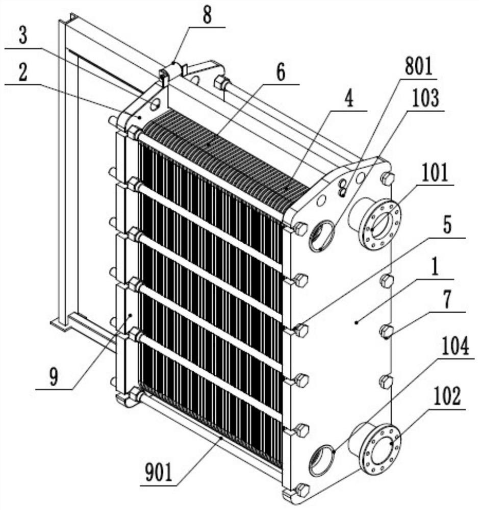
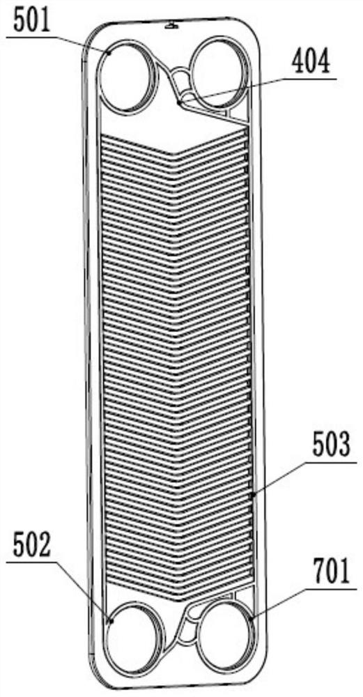
The invention relates to the technical field of plate heat exchangers, in particular to a leakage-proof synergistic plate heat exchanger which comprises a first plate, a second plate, a guide rod, a first plate piece, a first sealing assembly, an alarm device, a second plate piece and a second sealing assembly. According to the leakage-proof synergistic plate heat exchanger of the scheme, in orderto make a medium conveniently flow on the first plate piece, a corrugated structure is arranged on the first plate piece, the corrugated structure can increase the contact area of the medium and thefirst plate piece, meanwhile decrease the flowing speed of the medium on the first plate piece, and prolong the heat transfer time of the medium and the first plate piece, thereby improving the heat exchange efficiency.

Description

technical field [0001] The invention relates to the technical field of plate heat exchangers, in particular to a leak-proof and efficient plate heat exchanger. Background technique [0002] Introduction: The plate heat exchanger is a high-efficiency heat exchanger composed of a series of metal sheets with a certain corrugated shape. Thin rectangular channels are formed between various plates, and heat exchange is performed through the plates. Plate heat exchanger is an ideal equipment for liquid-liquid, liquid-vapor heat exchange. It has the characteristics of high heat exchange efficiency, small heat loss, compact and light structure, small footprint, wide application, and long service life. However, the existing plate heat exchangers are prone to internal leakage after long-term use, which affects Thermal performance, in severe cases, it will cause adverse reactions such as corrosion, explosion or severe toxicity. The specific reasons for the internal leakage phenomenon ...

Claims


Application Information

Patent Timeline
IPC IPC(8): F28D9/00F28F3/04F28F3/10F28F11/02F28F27/00
CPCF28D9/0037F28F3/046F28F3/10F28F11/02F28F27/00
Inventor 钱忠华
Owner 钱忠华
Learn More