Polishing equipment and method without subsurface damage

A technology of subsurface damage and equipment, which is applied in the field of non-subsurface damage polishing equipment, can solve problems such as subsurface damage of optical components, and achieve the effects of improving surface quality, increasing ionization rate, and high efficiency

Inactive Publication Date: 2021-01-08
AEROSPACE SCI & IND MICROELECTRONICS SYST INST CO LTD
View PDF5 Cites 2 Cited by
  • Summary
  • Abstract
  • Description
  • Claims
  • Application Information

AI Technical Summary

Problems solved by technology

Represented by non-contact polishing methods such as neutral ion beam polishing and plasma-assisted chemical polishing, these technologies can obtain better surface shape accuracy and surface quality, but in the process of generating plasma, high-energy ions will be generated to continuously bombard the material Surface, resulting in physical sputtering effects, which will generate new subsurface damage to the processed optical components

Method used


Image

  • Polishing equipment and method without subsurface damage
  • Polishing equipment and method without subsurface damage

Examples


Embodiment 1

[0035] Polishing experiment of subsurface damaged layer of fused silica:

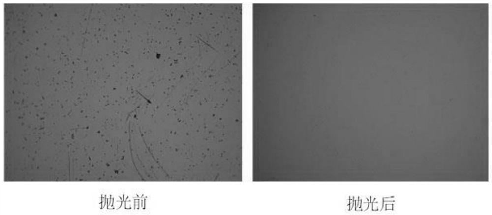
[0036] Step 1: Ultrasonic cleaning is performed on the fused silica sample to be tested, and the surface of the fused silica is immersed in 10% HF acid solution for 10 minutes to expose the subsurface damage layer, and the subsurface damage is observed with a microscope;

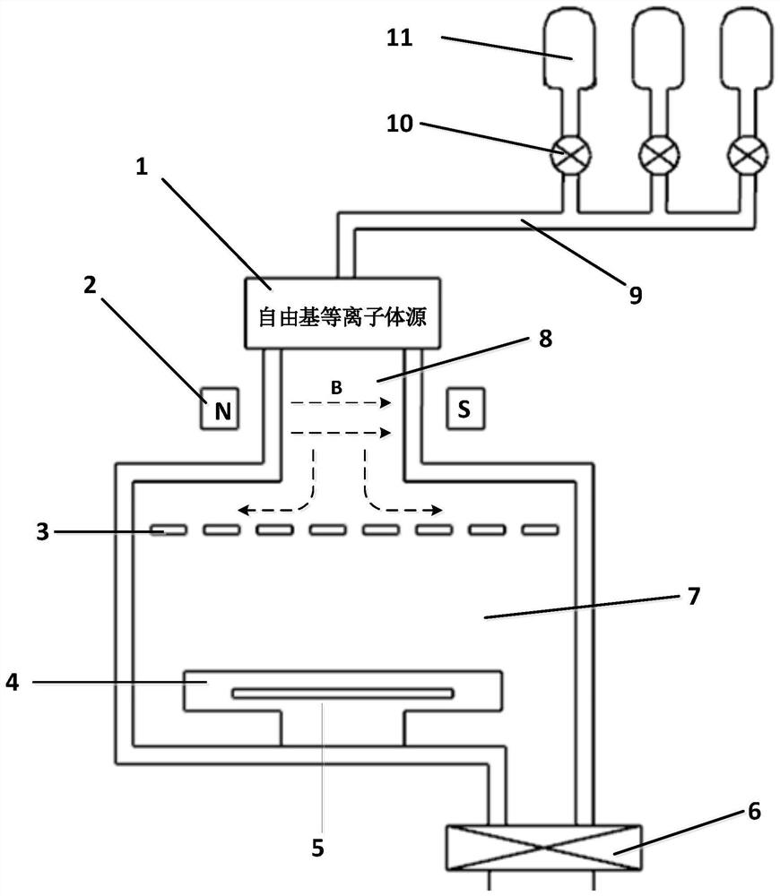
[0037] Step 2: Open the vacuum cover of the polishing chamber, place the fused silica on the polishing base, cover the vacuum cover, and use the exhaust system to reduce the vacuum degree of the polishing chamber to 10-3Pa;

[0038] Step 3: Fill in the working gas, carbon tetrafluoride 500sccm, oxygen 100sccm, use the voltage stabilization system to stabilize the vacuum at 50Pa, turn on the microwave plasma source, adjust the microwave power to 2000W, start glow discharge, and generate plasma. The device starts to work;

[0039] Step 4: Process for about 40 minutes, close the device, inflate, open the vacuum polishing chamber, take o...


PUM


Abstract

The invention discloses polishing equipment without subsurface damage. The polishing equipment comprises a plasma generating device, a magnetic field device, a high-energy charged ion binding cavity and a processing polishing vacuum cavity, wherein high-energy charged ions generated by the plasma generating device are bound and isolated in the high-energy charged ion binding cavity outside a polishing area in the processing polishing vacuum cavity through a magnetic field generated by the magnetic field device, and free radical plasma active groups generated by the plasma generating device enter the polishing area in the processing polishing vacuum cavity to realize polishing and the like. According to the polishing equipment, the number of the high-energy charged ions in a process cavityis effectively reduced, the bombardment sputtering effect of the high-energy ions on the surface of an optical element is greatly reduced, a subsurface damage layer of the optical element can be effectively removed, and the surface quality of the optical element is obviously improved.

Description

technical field [0001] The invention relates to the field of optical processing, and more specifically, to a non-subsurface damage polishing device and method. Background technique [0002] With the development of modern short-wave optics, strong light optics, electron optics and thin film science, the surface quality requirements of the required materials are getting higher and higher. In the high-tech field, the demand for high-quality optical components is also increasing day by day. This situation puts forward higher requirements for the ability to process and manufacture optical components. [0003] Subsurface damage of optical components is the microcracks, fractures, deformations and other defects lurking under the surface of optical components, which will cause light scattering and signal loss, and increase the damage threshold of laser light. For high-performance optical components, such as laser gyro systems and laser mirrors, there are generally strict requiremen...

Claims


Application Information

Patent Timeline
IPC IPC(8): B24B1/00
CPCB24B1/00
Inventor 武春风李坤吴丰阳马社泽小平梁国斌
Owner AEROSPACE SCI & IND MICROELECTRONICS SYST INST CO LTD
Why Eureka
Try Eureka