Novel-configuration tilt rotor aircraft and flight control method thereof

A technology of tilting rotors and aircraft, applied in the field of aircraft, can solve the problems of forward flight speed limit, forward blade shock wave, difficult balance of fuselage moment, etc., and achieve the effects of reducing lift loss, flying fast and improving stability

Active Publication Date: 2021-01-19
NANJING UNIV OF AERONAUTICS & ASTRONAUTICS
View PDF5 Cites 4 Cited by
  • Summary
  • Abstract
  • Description
  • Claims
  • Application Information

AI Technical Summary

Problems solved by technology

[0003] Among them, the wing size of traditional fixed-wing aircraft is large, the overall volume is large, and it takes up a lot of space when it is on the ground, and it is inconvenient to transport and carry.
and takeoff requires a runway of some distance
Although the rotorcraft can take off and land vertically, when the speed of the rotorcraft is too fast, the forward blades often generate shock waves, and the backward blades will stall, resulting in a limitation of the maximum forward flight speed
The tilt rotor aircraft is a new type of aircraft that combines the characteristics of fixed-wing aircraft and helicopters. It has the advantages of fixed-wing high-speed cruise and helicopter vertical take-off and landing and hovering. The wing section will block part of the rotor downwash airflow, resulting in a decrease in the lift of the whole machine
Moreover, the airflow under the fixed wing is turbulent during the tilting process, especially the fuselage moment is difficult to balance during the tilting process, which makes it more difficult to control the attitude of the tiltrotor aircraft body

Method used


Image

  • Novel-configuration tilt rotor aircraft and flight control method thereof
  • Novel-configuration tilt rotor aircraft and flight control method thereof
  • Novel-configuration tilt rotor aircraft and flight control method thereof

Examples


Embodiment 1

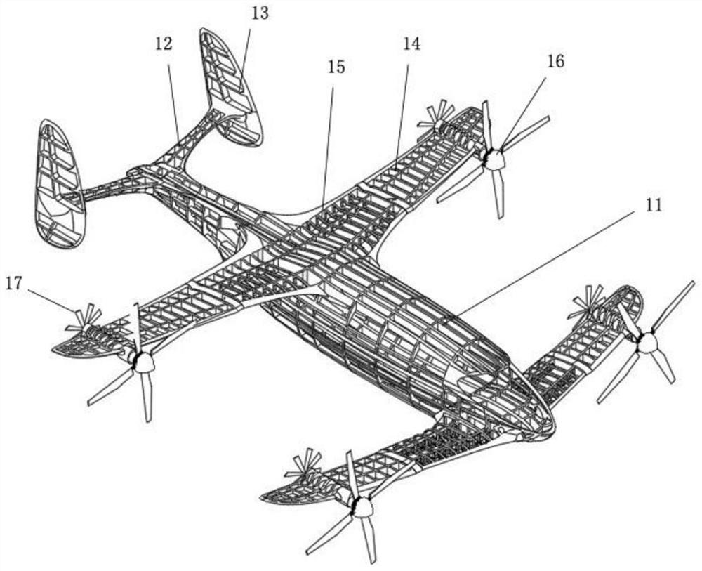
[0038] attached figure 1 It is the level flight state diagram of the tiltable and foldable rotorcraft of the present invention. In this state, the forward pulling force can be provided by the front rotor system 16, and the forward thrust can also be provided by the rear end propeller system 17 simultaneously. The wing system provides the lift of the aircraft.

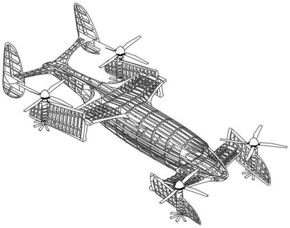
[0039] attached figure 2 It is a vertical flight state diagram of the tiltable and foldable rotorcraft of the present invention. At this time, the upper outer section wing 14 is in the backward folding state, and the lower side outer section wing is in the forward folding state. The rotor system 16 controls the collective pitch and the cyclic pitch to control the aircraft.

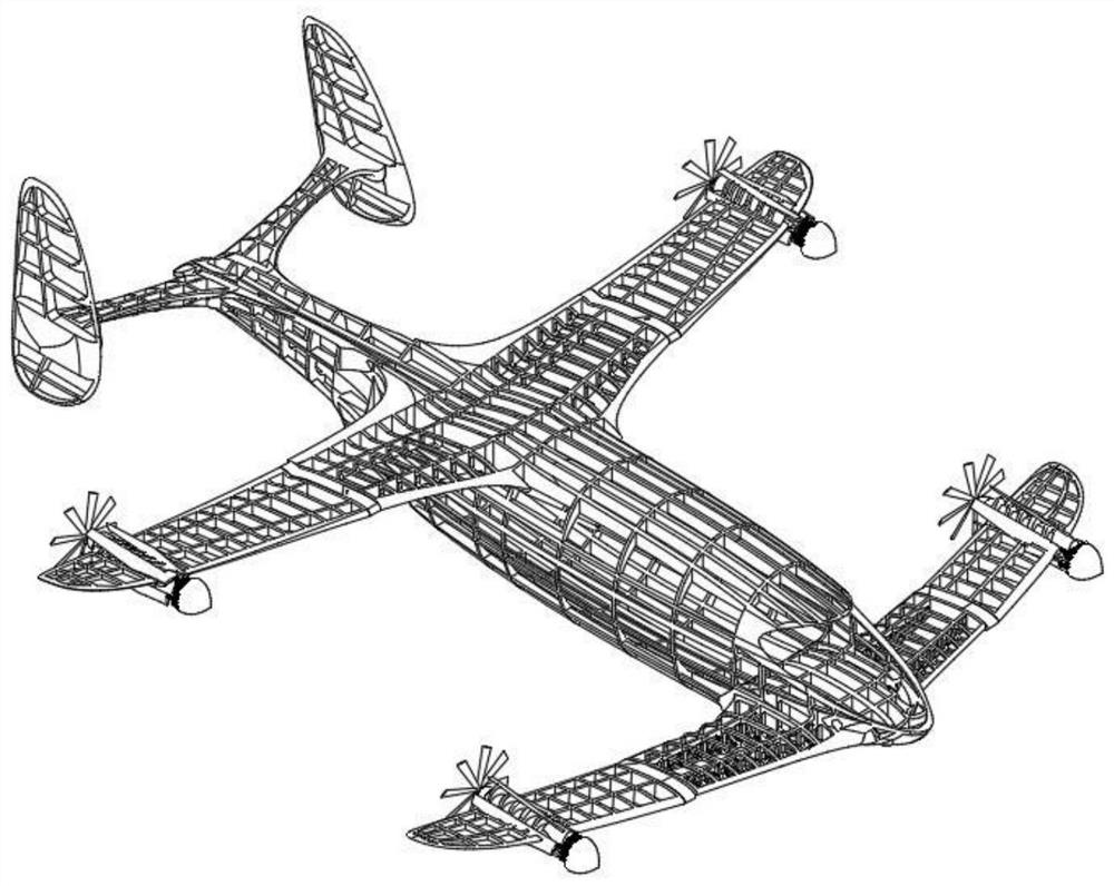
[0040] attached image 3 It is a schematic diagram of a tiltable and foldable rotorcraft flying forward at high speed. In this state, the blades of the rotor system 16 are folded, which can reduce the resistance brought by the rotor system when ...

Embodiment 2

[0043] The aircraft is in the tilting transition section, and the aircraft gradually builds up its forward flight speed. At this time, the lift provided by the rotor gradually decreases, and the lift provided by the wings gradually increases. At the same time, the resistance of the rotor increases further, and the propeller starts to intervene. After the aircraft has fully established its forward flight speed, the lift of the aircraft is provided by the fixed wings. At this time, the rotor brakes and stops working, and is retracted by the folding mechanism on both sides of the fuselage. At the same time, the propellers enter the working state to provide the thrust for the aircraft in level flight . And the process of converting from level flight to vertical take-off and landing is opposite to the above-mentioned process.

Embodiment 3

[0045] In order to realize the rotation of the wing in two directions simultaneously in one rotation action, a special plane angle is designed in this example, so that the feeding mechanism can be realized in one rotation action. The key to this design is to design the special angle of the slope of the tilting mechanism. Calculated by the method of solid geometry, two key design angles can be obtained as follows: Figure 9 and Figure 10 As shown, that is, from the top view, the angle between the inclined plane and the horizontal is From the side view, the angle between the slope and the horizontal plane is After the verification of the geometric model, the angle design can meet the design requirements proposed above. The specific angle and the specific component relationship of the working state are as attached Figure 9 And attached Figure 10 shown in .

[0046] The position of the folding mechanism in the whole aircraft is as attached Figure 11 attached Figure ...


PUM


Abstract

The invention provides a novel-configuration tilt rotor aircraft and a flight control method thereof. According to the aircraft, a conventional vertical fin and horizontal fin are arranged at the tailof an aircraft body, and two sets of wings are arranged on the two sides of the middle of the aircraft body. Each wing comprises an inner-section wing and an outer-section wing which are connected through a folding mechanism, and a set of foldable rotors is arranged at the tail end of each outer-section wing; and the outer-section wings can simultaneously finish two actions of folding and rotating around the inner-section wings through the folding mechanisms. When the aircraft vertically takes off and lands, the obstruction of wings to the downwash flow of the rotor wings can be reduced; on the other hand, the body size and the projection area can be reduced. When the aircraft flies in the air, the wings are unfolded, the rotor wings are folded, resistance brought by the rotor wings during high-speed forward flight can be effectively reduced, and therefore the forward flight speed is increased.

Description

technical field [0001] The invention relates to the field of aircraft, in particular to a new configuration tilt rotor aircraft and a flight control method thereof. Background technique [0002] Aviation technology and equipment play an important role in both the military and civilian fields. From a military point of view, the lack of air supremacy will expose the military equipment and personnel of the army and navy to enemy air strikes, making it difficult to organize effective attacks and defenses. From the perspective of civilian use, advanced civil aircraft can make people's travel more convenient, and with the emergence of drones, forest firefighting, agricultural plant protection, etc., the aviation field has become more and more important. [0003] Among them, the wing size of traditional fixed-wing aircraft is large, and the overall volume is large, which takes up a lot of space when it is on the ground, and is inconvenient to transport and carry. And take off req...

Claims


Application Information

Patent Timeline
Patent Type & Authority Applications(China)
IPC IPC(8): B64C27/22B64C3/56B64C27/52G05D1/08
CPCB64C27/22B64C3/56B64C27/52G05D1/0808
Inventor 高亚东黄大伟
Owner NANJING UNIV OF AERONAUTICS & ASTRONAUTICS
Why Eureka
Try Eureka