Network device capable of supporting photoelectric switching and network server
A network server and network device technology, which is applied in the field of network devices and network servers that can support photoelectric switching, can solve the problems of non-recovery, increased power cost, fire and burn, etc., to achieve convenient and effective heat dissipation and cooling, improve power consumption efficiency, cost reduction effect
- Summary
- Abstract
- Description
- Claims
- Application Information
AI Technical Summary
Problems solved by technology
Method used
Image


Examples
Embodiment 1
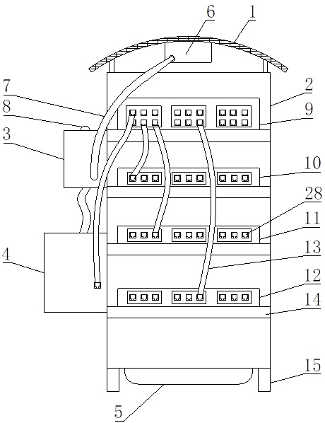
[0029] Such as Figure 1-Figure 6 As shown, the present invention provides a network device and network server that can support photoelectric switching, including an installation cabinet 2, a photovoltaic panel 1 is arranged above the installation cabinet 2, a photoelectric switch 3 is arranged on the right side of the installation cabinet 2, and a photoelectric switch 3 is arranged on the right side of the installation cabinet 2. A network protector 4 is arranged below the switcher 3, a cooling chamber 5 is arranged at the bottom of the installation cabinet 2, support legs 15 are arranged at four corners of the bottom of the installation cabinet 2, an energy converter 6 is arranged above the installation cabinet 2, and the installation cabinet 2 The right side is provided with photoreceptor 8.
[0030] In this embodiment, the photovoltaic panel 1 is used to collect light energy, converted by the energy converter 6, and then through the cooperation of the photoelectric switch ...
Embodiment 2
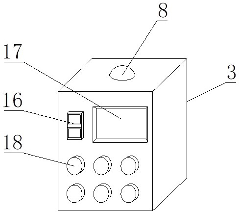
[0034] Such as Figure 1-Figure 6 Shown, on the basis of embodiment 1, the present invention provides a kind of technical scheme: the top of photoelectric switch 3 is provided with photoreceptor 8, and the front of photoelectric switch 3 is provided with switcher switch 16, and the top of photoelectric switch 3 The front is provided with a switcher screen 17, the front of the photoelectric switcher 3 is provided with a switching button 18, the switcher switch 16 is arranged on the left side of the switcher screen 17, the switcher screen 17 is arranged on the top of the switching button 18, and the switching button 18 is set Below the switch 16, the front of the network protector 4 is provided with a protector screen 19, the front of the network protector 4 is provided with a protector indicator light 20, and the front of the network protector 4 is provided with a reset key 21, and the network protector 4 is provided with a reset button 21. The front of 4 is provided with an ai...
Embodiment 3
[0036] Such as Figure 1-Figure 6 As shown, on the basis of Embodiment 1 and Embodiment 2, the present invention provides a technical solution: the inner side of the network protector 4 is provided with a mounting base, the top of the mounting base is fixedly installed with a current limiter 27, and the current limiter 27 The back is provided with a network interface 28, the top of the current limiter 27 is provided with a network transformer 26, the inner side of the heat dissipation chamber 5 is provided with a radiator 24, the top of the radiator 24 is provided with a rotating shaft, and the outer wall of the rotating shaft is evenly distributed with cooling fan blades 25, The inboard of installation cabinet 2 is provided with database 9, and the bottom of database 9 is provided with mounting plate 14, and the below of database 9 is provided with main server 10, and the bottom of main server 10 is provided with mounting plate 14, and the below of main server 10 is provided w...
PUM
 Abstract
Description
Claims
Application Information