R(Fe,M)12 type rare earth permanent magnet material and preparation method thereof

A technology of rare earth permanent magnets and rare earth elements, which is applied in the fields of magnetic materials, inductance/transformer/magnet manufacturing, magnetic objects, etc., can solve the problems of lack of grain boundary phase structure in magnetic alloys, difficulty in preparing high-performance bulk magnetic materials, etc., and achieve The effect of small rare earth ratio, cost reduction, and rare earth resources saving

Pending Publication Date: 2021-01-22
NANJING UNIV OF SCI & TECH
View PDF0 Cites 1 Cited by
  • Summary
  • Abstract
  • Description
  • Claims
  • Application Information

AI Technical Summary

Problems solved by technology

while R(Fe,M) 12 Type magnetic alloys lack effective grain boundary phase structure, which is one

Method used


Image

  • R(Fe,M)12 type rare earth permanent magnet material and preparation method thereof
  • R(Fe,M)12 type rare earth permanent magnet material and preparation method thereof

Examples


preparation example Construction

[0028] a R(Fe,M) 12 The preparation method of the rare earth permanent magnet material of type, concrete steps are as follows:

[0029] (1) According to the stoichiometric atomic percentage R(Fe,M) 12 Ingredients, where R is a rare earth element and M is a transition element. Rare earth elements R are in excess of 5-20% during batching, and the purity of rare earth raw materials is greater than 99.5%. Mixed rare earths with a certain ratio can also be used to reduce costs.

[0030] (2) The prepared R(Fe,M) 12 Alloy raw materials are put into the smelting furnace, and the vacuum degree reaches 10 -2 Start heating when the Pa is above, and wait until the vacuum degree reaches 10 again. -2When the pressure in the furnace reaches -0.05MPa, adjust the power of the smelting furnace to the smelting power for smelting. After the alloy raw materials are completely melted, stir for 5-10 minutes. After refining, the alloy The liquid is poured on a water-cooled copper roll to obtain ...

Embodiment 1

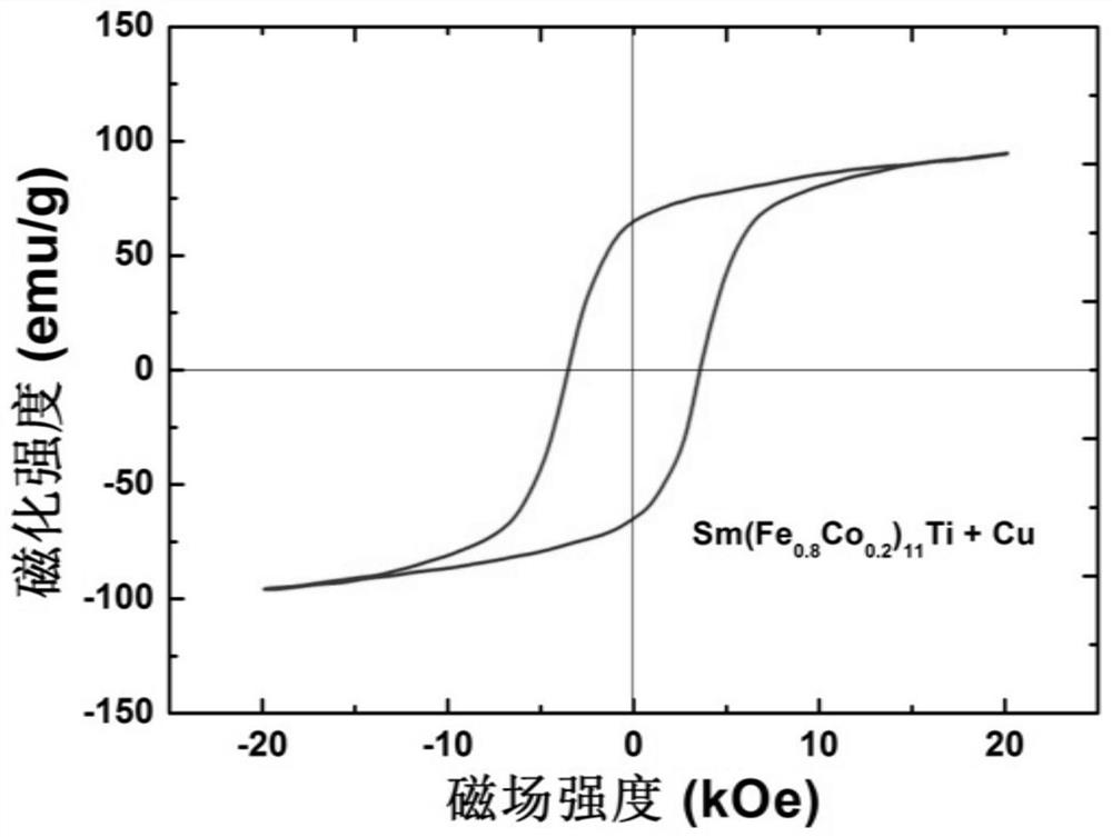
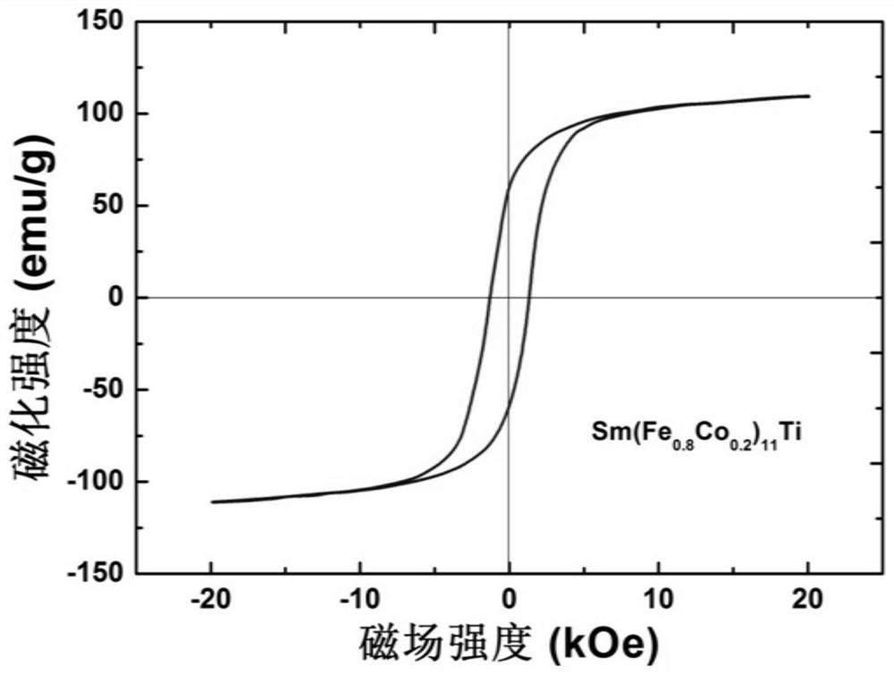
[0035] (1) According to the chemical formula Sm(Fe 0.8 co 0.2 ) 11 Ti batching, the raw materials used are rare earth Sm with a purity greater than 99.5%, pure Fe, Co, Ti with a purity greater than 99.9%, and Sm in excess of 10%.

[0036] (2) The prepared Sm(Fe 0.8 co 0.2 ) 11 Put the Ti alloy raw material into the melting quick-setting crucible in the medium-frequency induction furnace, and when the vacuum degree reaches 10 -2 When Pa is above, power on and preheat until the vacuum degree reaches 10 again. -2 Stop vacuuming after Pa is above and fill with high-purity Ar gas. When the Ar pressure in the furnace reaches -0.05MPa, adjust the power of the melting furnace to the melting power for smelting. After all the raw materials are melted, stir and refine for 3 minutes. After refining, pour the alloy liquid onto a water-cooled copper roll to obtain Sm(Fe 0.8 co 0.2 ) 11 Ti alloy flakes.

[0037] (3) Sm(Fe 0.8 co 0.2 ) 11 After the Ti quick-quenching alloy is coa...


PUM

PropertyMeasurementUnit
Average particle sizeaaaaaaaaaa
Saturation magnetizationaaaaaaaaaa

Abstract

The invention belongs to the field of permanent magnet materials, and particularly relates to an R(Fe,M)12 type rare earth permanent magnet material and a preparation method thereof. According to theinvention, a Cu-rich grain boundary phase of a magnet is designed through a magnetic powder surface chemical Cu plating process, a hot-pressed magnet is prepared, the coercive force of the magnet is improved, and preparation of the novel R(Fe,M)12 hot-pressed block permanent magnet is achieved; through Cu plating treatment on the surface of the magnetic powder, the Cu-rich grain boundary phase perfectly coating grains can be formed in the hot-pressed magnet, so that the purpose of magnetic isolation between R(Fe,M)12 hard magnetic phase grains can be effectively achieved, reverse magnetizationdomain extension is inhibited, and the permanent magnet characteristic of the magnet is improved; and the grain boundary Cu-rich phase can also greatly improve the electrochemical potential of the grain boundary corrosion channel of the magnet, effectively improve the intrinsic corrosion resistance of the magnet and prolong the actual service life of the magnet.

Description

technical field [0001] The invention belongs to the field of permanent magnet materials, in particular to an R(Fe,M) 12 Type rare earth permanent magnet material and preparation method thereof. Background technique [0002] In 1983, the Japanese M. Sagawa reported the third generation of rare earth permanent magnets - Nd 2 Fe 14 B, it is known as the "Magnetic King" by virtue of its room temperature magnetic energy product unmatched by other magnetic materials. Currently, Nd 2 Fe 14 B rare earth permanent magnet materials have been widely used in many fields, such as nuclear magnetic resonance imaging in medical systems, computer hard disk drives, miniature electroacoustic equipment, etc. With the increasing number of environmentally friendly industries, Nd-Fe-B permanent magnets also play an increasingly important role in wind power generation, hybrid vehicles and other fields. However, the production and preparation of Nd-Fe-B rare earth permanent magnets need to con...

Claims


Application Information

Patent Timeline
IPC IPC(8): H01F1/053H01F41/00B22F1/02B22F3/14
CPCH01F1/0536H01F41/00B22F3/14B22F1/17
Inventor 张玉晶赵惠琨姚旻皓徐锋缪雪飞邵艳艳
Owner NANJING UNIV OF SCI & TECH
Why Eureka
Try Eureka