
Biomass continuous pyrolysis carbonization device and biomass continuous pyrolysis carbonization method

A pyrolysis carbonization and biomass technology, applied in combustion methods, biofuels, incinerators, etc., can solve the problems of increasing production costs and equipment quantity, increasing the investment of the overall equipment, and poor utilization of pyrolysis production capacity. Small footprint, high production efficiency and compact device

Inactive Publication Date: 2021-01-26
DALIAN MARITIME UNIVERSITY
View PDF2 Cites 0 Cited by
  • Summary
  • Abstract
  • Description
  • Claims
  • Application Information

AI Technical Summary

Problems solved by technology

[0002] At present, most biomass carbonization production processes adopt carbonization processes such as vertical intermittent heating pyrolysis and single-screw propulsion external heating continuous pyrolysis, with limited output and unstable quality control; large energy consumption, poor utilization of its own pyrolysis capacity, and It will produce serious "three wastes" pollution, and further treatment is required to meet the emission standards; it not only increases the production cost and the number of equipment, but also increases the investment of the overall device

Method used


Image

  • Biomass continuous pyrolysis carbonization device and biomass continuous pyrolysis carbonization method
  • Biomass continuous pyrolysis carbonization device and biomass continuous pyrolysis carbonization method
  • Biomass continuous pyrolysis carbonization device and biomass continuous pyrolysis carbonization method

Examples


Embodiment 1

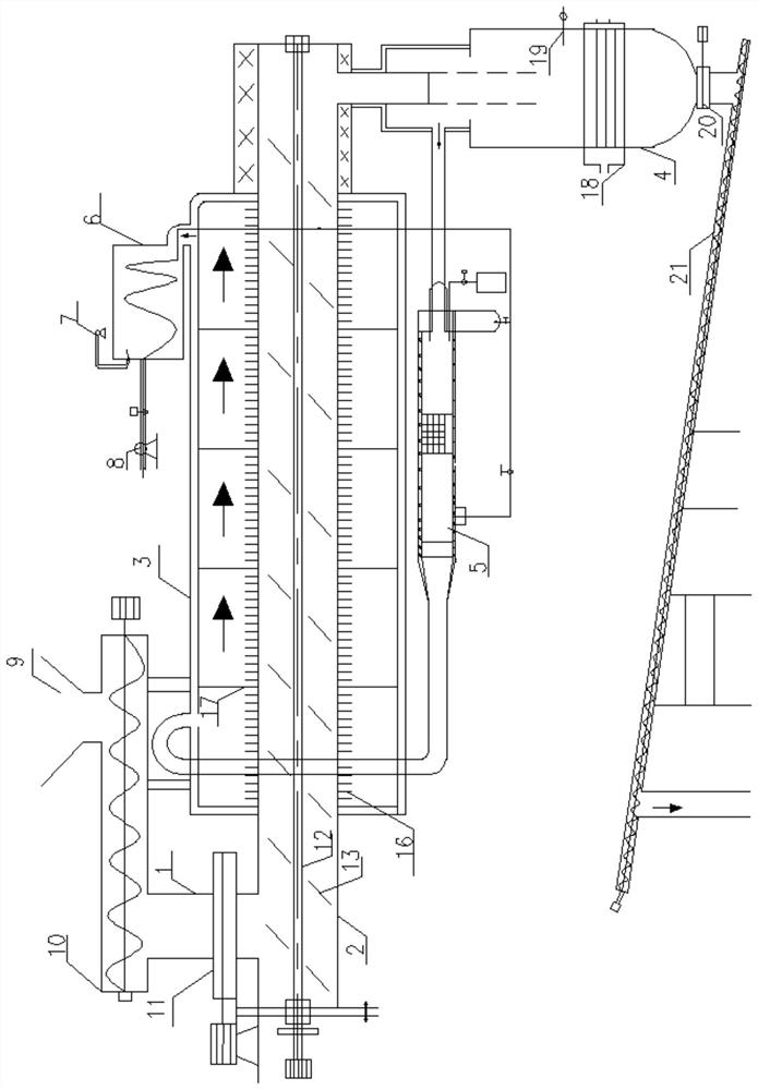
[0033] A biomass continuous pyrolysis carbonization device, the structure is as follows figure 1 As shown, the device includes a quantitative feeder 1, a pyrolysis carbonization chamber 2, a gas-solid separator 4, a burner 5, a heat exchanger 6, an induced draft fan 7, and a blower 8;

[0034] The quantitative feeder 1 is connected with the feed port of the pyrolysis carbonization chamber 2, the gas-solid separator 4 is connected with the discharge port of the pyrolysis carbonization chamber 2, the burner 5 is connected with the gas-solid separator 4 The gas outlet is connected, the burner 5 is equipped with a ceramic body, the flue gas output pipe of the burner 5 is connected to the outer heating sleeve 2, the inlet I of the heat exchanger 6 is connected to the outer heating sleeve 3 The flue gas outlet is connected, the induced draft fan 7 is connected to the outlet I of the heat exchanger 6, the blower 8 is connected to the inlet II of the heat exchanger 6, and the outlet ...

Embodiment 2

[0040] The pyrolysis carbonization method of device described in embodiment 1, described method comprises the steps:

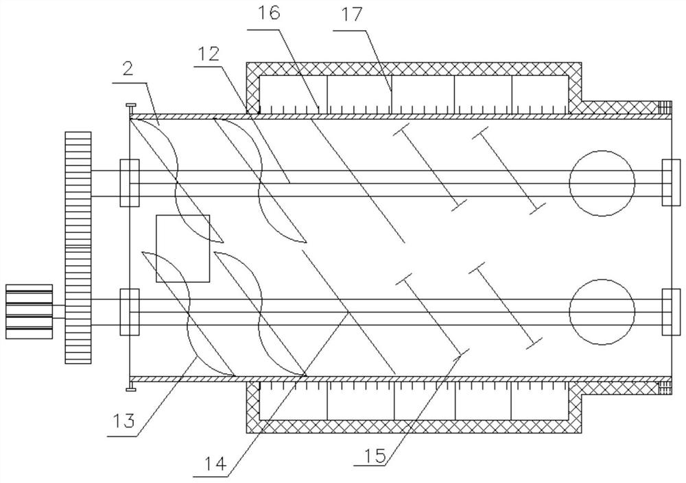
[0041] (1) Biomass is continuously fed into the pyrolysis and carbonization chamber 2 through the quantitative feeder 1, and the material is pushed into the dehydration, pyrolysis, and carbonization areas by the pusher blade 13, the stirring blade 14, and the scraper blade 15, and is then pyrolyzed and carbonized. Finally, biochar and mixed gas are produced;

[0042] (2) Biochar and mixed gas produced after carbonization enter the gas-solid separator 4 through the discharge port of the pyrolysis carbonization chamber 2;

[0043] (3) The mixed gas is introduced into the burner by the induced draft fan 7 and burned for the first time, and the tar and wood vinegar in the mixed gas are further decomposed by the action of the ceramic body, and then burned for the second time;

[0044] (4) The high-temperature flue gas produced after combustion enters the outer hea...


PUM


Abstract

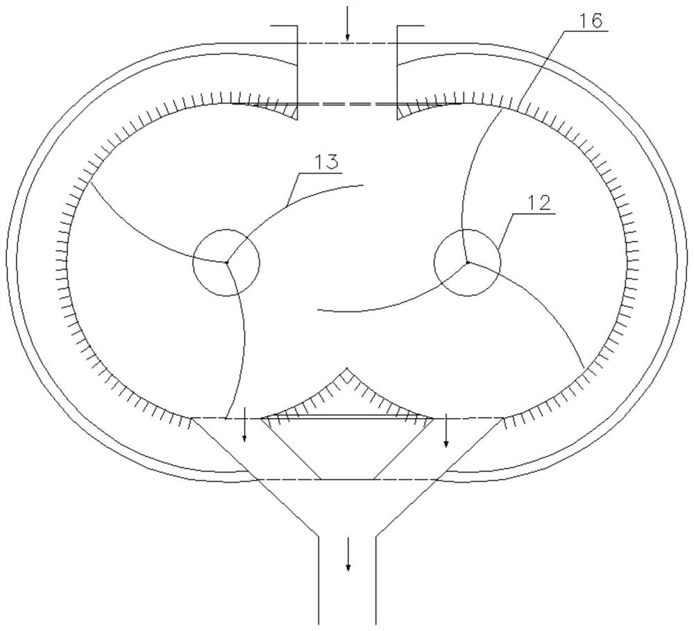
The invention relates to a biomass continuous pyrolysis carbonization device and a biomass continuous pyrolysis carbonization method, and belongs to the field of environmental protection and resourceutilization. The device comprises a pyrolysis carbonization chamber, wherein the cross section of the pyrolysis carbonization chamber is in a shape similar to a horizontal 8 shape formed by butting two C-shaped cylinders, the two C-shaped cylinders communicate with each other, a respective rotating shaft is arranged in each C-shaped cylinder, and a pushing blade, a stirring blade and a wall scraping blade are arranged on each rotating shaft. The device is compact, short in technological process, small in occupied area, high in production efficiency and free of emission of three wastes, and heat energy can be effectively utilized.

Description

technical field [0001] The invention relates to a biomass continuous pyrolysis carbonization device and a method thereof, belonging to the field of environmental protection and resource utilization. Background technique [0002] At present, most biomass carbonization production processes adopt carbonization processes such as vertical intermittent heating pyrolysis and single-screw propulsion external heating continuous pyrolysis, with limited output and unstable quality control; large energy consumption, poor utilization of its own pyrolysis capacity, and Serious "three wastes" pollution will be generated, and further treatment is required to meet the emission standards; it not only increases the production cost and the number of equipment, but also increases the investment of the overall device. Contents of the invention [0003] The object of the present invention is to provide a biomass continuous pyrolysis carbonization device and its method in order to solve the above...

Claims


Application Information

Patent Timeline
Patent Type & Authority Applications(China)
IPC IPC(8): C10B53/02C10B57/00F23G7/07
CPCC10B53/02C10B57/00F23G7/07Y02E50/10
Inventor 李清波段锡黎
Owner DALIAN MARITIME UNIVERSITY
Learn More