Technological method applied to guaranteeing micro-milling machining precision of folded waveguide slow-wave structure

A technology of slow-wave structure and folded waveguide, which is applied in metal processing equipment, metal processing machinery parts, milling machine equipment, etc., can solve the problems of restricting the size, shape and position accuracy of slow-wave structures, so as to ensure the consistency of depth and improve the vertical degree of effect

Active Publication Date: 2021-01-29
HARBIN INST OF TECH
View PDF8 Cites 1 Cited by
  • Summary
  • Abstract
  • Description
  • Claims
  • Application Information

AI Technical Summary

Problems solved by technology

However, many factors such as the positioning accuracy, repeat positioning accuracy, and contour following accuracy of the machine tool will largely restrict the improvement of the slow wave structure size, shape, and position accuracy.

Method used


Image

  • Technological method applied to guaranteeing micro-milling machining precision of folded waveguide slow-wave structure
  • Technological method applied to guaranteeing micro-milling machining precision of folded waveguide slow-wave structure
  • Technological method applied to guaranteeing micro-milling machining precision of folded waveguide slow-wave structure

Examples


Embodiment 1

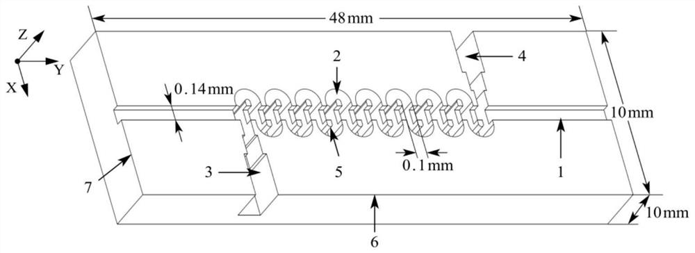
[0070] A process method applied to the micro-milling of folded waveguide slow-wave structures to ensure the machining accuracy, which is used for machining such as figure 1 The slow-wave structure shown. The overall slow-wave structure is a cuboid of 48mm*10mm*10mm. S-shaped grooves 2 and straight grooves 1 that penetrate each other are distributed on the upper surface of the cuboid, and the two intersect to form isolated islands 5 . Among them, the S-shaped groove has a total of 75 cycles, the aspect ratio of the S-shaped groove reaches 255 μm / 100 μm, the width of the island is 48 μm, the span is 22.2 mm, and the width of the straight groove is 140 μm. The material of the slow-wave structure is doped with Al with a volume fraction of 0.5% to 1.2% and a particle size of 50 to 100 nm. 2 O 3 Particles of dispersed oxygen-free copper. The dimensional accuracy of the processed slow-wave structure is required to be better than ±2μm, and the surface roughness Ra should be better...

Embodiment 2

[0076] A process method applied to the micro-milling of folded waveguide slow-wave structures to ensure the machining accuracy, which is used for machining such as figure 1 The slow-wave structure shown. The overall slow-wave structure is a cuboid of 48mm*10mm*10mm. S-shaped grooves 2 and straight grooves 1 that penetrate each other are distributed on the upper surface of the cuboid, and the two intersect to form isolated islands 5 . Among them, the S-shaped groove has a total of 75 cycles, the aspect ratio of the S-shaped groove reaches 255 μm / 100 μm, the width of the island is 48 μm, the span is 22.2 mm, and the width of the straight groove is 140 μm. The material of the slow-wave structure is doped with Al with a volume fraction of 0.5% to 1.2% and a particle size of 50 to 100 nm. 2 O 3The dispersed oxygen-free copper of the particles, the volume fraction of the dispersed oxygen-free copper doping in this example is 1.1%. The dimensional accuracy of the processed slow-w...

Embodiment 3

[0122] Compared with the second embodiment, the basic requirements of the processed slow-wave structure are the same in this embodiment.

[0123] Compared with the second embodiment, the process steps of the present embodiment are omitted in step B1, the other steps are the same as the process method, and the cutting parameters are slightly adjusted within the selection range. The experimental results show that after using the process steps of this embodiment, ZYGO white light interferometer and VHX-1000 ultra-depth-of-field optical microscope are used to measure the dimensional accuracy and surface topography of the workpiece, and the shoulder burrs of the slow-wave microstructure are basically eliminated, and the adjacent processing units There is no obvious dislocation at the junction, the contour accuracy is good, the verticality of the side wall is high, and the thin-walled island structure has no local collapse. Within, the surface roughness Ra is better than 60nm. The ...


PUM


Abstract

The invention relates to a technological method applied to guaranteeing the micro-milling machining precision of a folded waveguide slow-wave structure. The technological method comprises the steps that the outer edge of a to-be-machined area of a workpiece blank is subjected to micro-milling machining, and an X-direction tool setting groove extending in the X-axis direction and a Y-direction toolsetting groove extending in the Y-axis direction are manufactured; after a tool is replaced in the micro-milling machining process, secondary tool setting of the tool in the X direction and the Y direction is correspondingly conducted with the X-direction tool setting groove and the Y-direction tool setting groove as the datum; and after the X-direction tool setting groove or/ and the Y-directiontool setting groove is/ are removed through micro-milling machining, secondary tool setting of the tool in the X direction or/ and the Y direction is/are conducted based on the side wall of the machined surface at the corresponding position. According to the technological method applied to guaranteeing the micro-milling machining precision of the folded waveguide slow-wave structure, the accuracyof the relative position during micro-milling machining of the slow-wave structure can be guaranteed, and the micro-milling machining precision is improved.

Description

technical field [0001] The invention relates to the technical field of ultra-precision micro-milling processing, in particular to a process method for ensuring the precision of micro-milling processing of a folded waveguide slow-wave structure. Background technique [0002] The slow-wave structure of the folded waveguide in the terahertz frequency band is the core part of the traveling wave tube amplifier. like figure 1 The shown slow-wave structure of the folded waveguide in the terahertz frequency band is a cuboid structure with a length of 48mm, a width of 10mm, and a height of 10mm. A straight band-shaped electron beam channel (hereinafter referred to as a straight groove) is machined along the central axis of the length direction of the upper surface of the cuboid. One end of the straight groove is set as the inlet, and the other end is set as the outlet. An S-shaped folded waveguide (hereinafter referred to as S-shaped groove) for transmitting terahertz waves is proc...

Claims


Application Information

Patent Timeline
Patent Type & Authority Applications(China)
IPC IPC(8): B23C3/00B23C9/00B23Q17/22H01J9/00H01J23/24
CPCB23C3/00B23C9/00B23Q17/22H01J9/00H01J23/24
Inventor 吴春亚李曦光陈明君刘畅侯博吴佳昊黄俊杰
Owner HARBIN INST OF TECH
Why Eureka
Try Eureka