
Lead-calcium-tin-copper rare earth grid alloy, positive grid and lead-acid storage battery

A technology of lead-acid batteries and rare earth alloys, which is applied in the direction of lead-acid batteries, battery electrodes, electrode carriers/collectors, etc., and can solve the problems that the grid is easy to prolong the battery life, hinder the normal charging and discharging of the battery, and affect the cycle performance of the battery. , to achieve good deep cycle performance, improve deep cycle performance, and reduce production costs

Inactive Publication Date: 2021-01-29
ANHUI LEOCH POWER SUPPLY
View PDF1 Cites 0 Cited by
  • Summary
  • Abstract
  • Description
  • Claims
  • Application Information

AI Technical Summary

Problems solved by technology

[0003] At present, the most widely used grid materials are lead-calcium alloy and lead-antimony alloy. In order to meet the requirements of battery sealing and less maintenance, the positive grid is required to have small oxygen evolution reaction and excellent corrosion resistance; in order to improve corrosion resistance and reduce Gas evolution reaction, lead-calcium-tin-aluminum alloy casting grids are usually used in the industry, but a passivation film is easily formed on the lower surface of the lead-calcium-tin-aluminum alloy grid during charging and discharging, which hinders the normal charging and discharging of the battery and affects the battery life. In addition, lead-calcium-tin-aluminum alloys under high temperature conditions cause the battery life to be greatly shortened due to factors such as fast corrosion rate of the grid and easy growth of the grid.

Method used


Image

  • Lead-calcium-tin-copper rare earth grid alloy, positive grid and lead-acid storage battery
  • Lead-calcium-tin-copper rare earth grid alloy, positive grid and lead-acid storage battery
  • Lead-calcium-tin-copper rare earth grid alloy, positive grid and lead-acid storage battery

Examples


Embodiment 1

[0032] The alloy includes the following components: 0.553% calcium; 1.55% tin; 0.0202% copper; 0.0229% lanthanum and the balance lead. The raw lead used in this implementation case is electrolytic lead with a material purity not lower than 99.994%, and the copper raw material is electrolytic copper with a purity not lower than 99.9935%.

[0033] Copper rare earth master alloy preparation: Add 35kg of electrolytic lead into the intermediate frequency furnace, melt it into lead liquid at 450°C, continue to heat up to 800-1100°C, remove scum and add 5.05kg of electrolytic copper and 5.725kg of lanthanum respectively according to the formula, and continue to stir Make it reach a eutectic state, then add 15kg of electrolytic lead, and slowly lower the temperature to about 600°C to cast ingots.

[0034] Preparation of lead-calcium-tin-copper rare-earth alloy: Add 35kg of electrolytic lead to the lead pot, melt it into lead liquid at 450°C, raise the temperature to 600-850°C, add 0.2...

Embodiment 2

[0040] The alloy includes the following components: 0.553% calcium; 1.55% tin; 0.0202% copper; 0.0229% cerium and the balance lead. The raw lead used in this implementation case is electrolytic lead with a material purity not lower than 99.994%, and the copper raw material is electrolytic copper with a purity not lower than 99.9935%.

[0041] Copper rare earth master alloy preparation: Add 35kg of electrolytic lead into the intermediate frequency furnace, melt it into lead liquid at 450°C, continue to heat up to 800-1100°C, remove scum and add 5.05kg of electrolytic copper and 5.725kg of cerium respectively according to the formula, and continue to stir Make it reach a eutectic state, then add 15kg of electrolytic lead, and slowly lower the temperature to about 600°C to cast ingots.

[0042] Preparation of lead-calcium-tin-copper rare-earth alloy: Add 35kg of electrolytic lead to the lead pot, melt it into lead liquid at 450°C, raise the temperature to 600-850°C, add 0.2765kg ...

Embodiment 3

[0048] The alloy includes the following components: 0.553% calcium; 1.55% tin; 0.0202% copper; 0.01% cerium, 0.01% lanthanum; The raw lead used in this implementation case is electrolytic lead with a material purity not lower than 99.994%, and the copper raw material is electrolytic copper with a purity not lower than 99.9935%.

[0049] Copper rare earth master alloy preparation: Add 35kg of electrolytic lead into the intermediate frequency furnace, melt it into lead liquid at 450°C, continue to heat up to 800-1100°C, remove scum and add electrolytic copper 5.05kg, lanthanum 2.83kg, cerium 2.83 kg, keep stirring to make it reach the eutectic state, then add 15kg of electrolytic lead, and slowly lower the temperature to about 600°C to cast ingots.

[0050] Preparation of lead-calcium-tin-copper rare-earth alloy: Add 35kg of electrolytic lead to the lead pot, melt it into lead liquid at 450°C, raise the temperature to 600-850°C, add 0.2765kg of calcium and 0.1kg of the prepared ...


PUM


Abstract

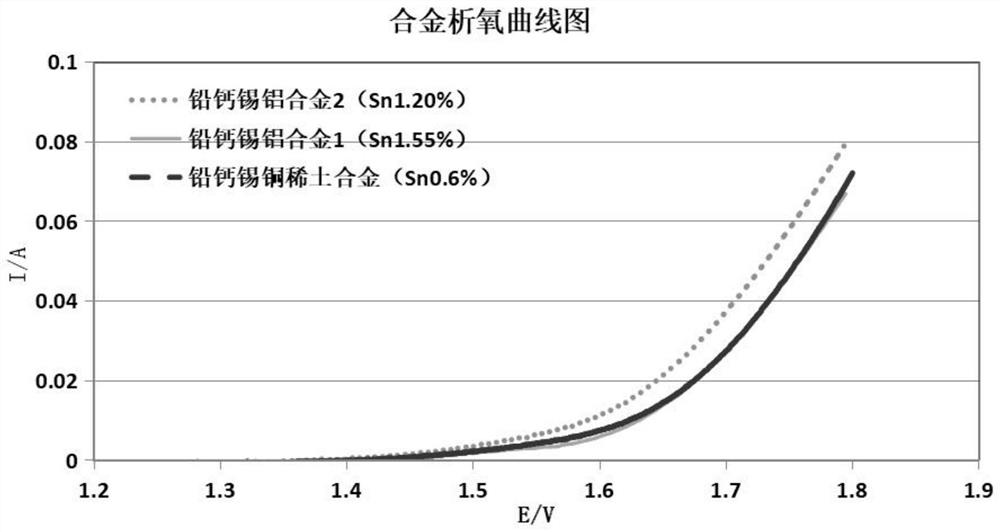
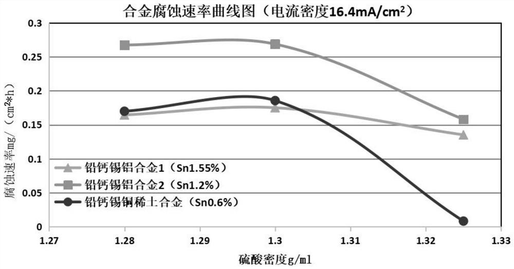
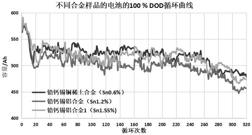
The invention relates to a lead-calcium-tin-copper rare earth grid alloy, a positive grid and a lead-acid storage battery. The lead-calcium-tin-copper rare earth grid alloy comprises the following components of, in weight by percentage, 0.04wt%-0.1wt% of calcium, 0.3wt%-1.0wt% of tin, 0.02wt%-0.06wt% of copper, 0.02wt%-0.2wt% of rare earth elements and the balance lead; and the method comprises the following steps of S1, dividing the required amount of electrolytic lead in claim 1 into two components, namely a component 1 and a component 2; S2, preparing copper rare earth master alloy; and S3,preparing the lead-calcium-tin-copper rare earth grid alloy. According to the lead-calcium-tin-copper rare earth grid alloy, the positive grid and the lead-acid storage battery, lanthanum and ceriumrare earth elements and copper elements are simultaneously added on the basis of the lead-calcium alloy which is widely used at present, so that the impedance of an oxide film on the surface of the grid can be effectively reduced, the deep cycle performance is improved, the growth of lead dioxide can be promoted, the corrosion resistance of the alloy is improved, good deep cycle performance and longer floating charge service life are realized, and meanwhile, the production cost is further reduced.

Description

technical field [0001] The invention belongs to the technical field of lead-acid batteries, in particular to a lead-calcium-tin-copper rare-earth alloy for positive grids of lead-acid batteries. Background technique [0002] A lead-acid battery is a device that can directly convert electrical energy and chemical energy. Its most important structure is the plate, and the grid in the plate plays a vital role: it is not only used as a carrier of active substances for It supports the skeleton and adheres to the active material, and also acts as a current conductor to gather and transmit the current and distribute the current evenly to the active material of the plate. [0003] At present, the most widely used grid materials are lead-calcium alloy and lead-antimony alloy. In order to meet the requirements of battery sealing and less maintenance, the positive grid is required to have small oxygen evolution reaction and excellent corrosion resistance; in order to improve corrosion ...

Claims


Application Information

Patent Timeline
Patent Type & Authority Applications(China)
IPC IPC(8): C22C11/06C22C1/03H01M4/68H01M4/73H01M10/06
CPCC22C1/03C22C11/06H01M4/685H01M4/73H01M10/06Y02E60/10
Inventor 侯娜娃张树祥豆江洪薛胜凡张波韩曦曦
Owner ANHUI LEOCH POWER SUPPLY
Learn More