Construction method of underground diaphragm wall in water-rich silty-fine sand layer

A water-rich powder fine sand layer and underground continuous wall technology, which can be used in excavation, sheet pile walls, foundation structure engineering, etc., and can solve the problems of increased construction costs and poor treatment effects

Inactive Publication Date: 2021-01-29
江苏旭辰交通科技发展有限公司
View PDF4 Cites 3 Cited by
  • Summary
  • Abstract
  • Description
  • Claims
  • Application Information

AI Technical Summary

Problems solved by technology

When the silty sand layer is shallow and thick, and the water level is high, especially for tank wall reinforcement and light well point dewatering, not only will the construction cost be increased, but the treatment effect will be poor

Method used


Image

  • Construction method of underground diaphragm wall in water-rich silty-fine sand layer
  • Construction method of underground diaphragm wall in water-rich silty-fine sand layer
  • Construction method of underground diaphragm wall in water-rich silty-fine sand layer

Examples


Embodiment Construction

[0029] The technical solutions of the embodiments of the present invention will be clearly and completely described below in conjunction with specific embodiments of the present invention.

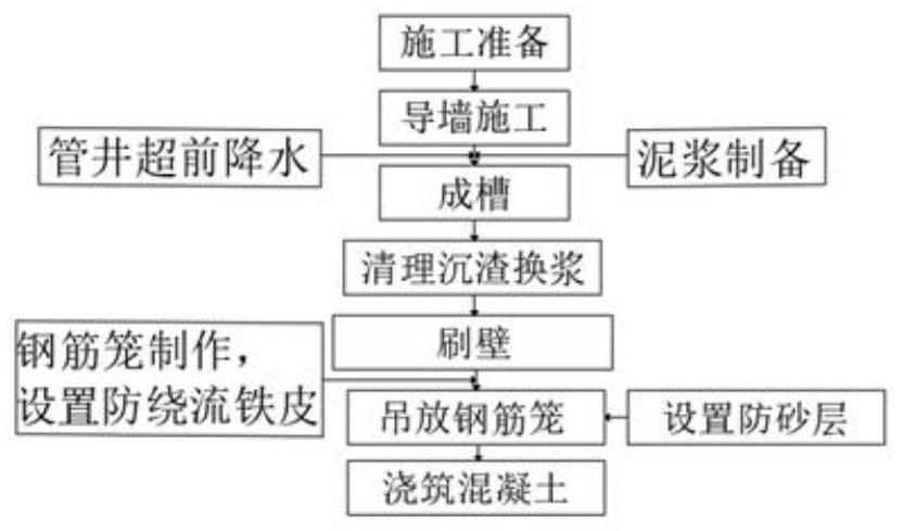
[0030] Such as figure 1 As shown, the construction method of a kind of water-rich powder fine sand layer underground continuous wall disclosed by the present invention comprises the following steps:

[0031] a. Guide wall construction, the sequence is: measurement and positioning, excavation, binding steel bars, formwork support, pouring, and formwork removal.

[0032] Technical points and construction points of guide wall:

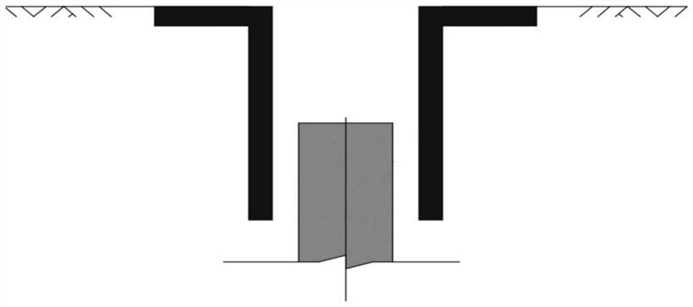
[0033] The guide wall is the reference object of the underground diaphragm wall on the ground surface. During the construction period, the guide wall must bear the static and dynamic loads of the steel cage, the conduit for pouring concrete, and the drilling rig, and at the same time ensure the accuracy of the construction position of the underground diaphragm wall. ...


PUM


Abstract

The invention discloses a construction method of an underground diaphragm wall in a water-rich silty-fine sand layer. The construction method comprises the following steps of guide wall construction,tube well advanced precipitation, slurry preparation, grooving, groove cleaning and slurry replacement, wall brushing, reinforcement cage manufacturing, reinforcement cage hoisting, sand prevention layer arrangement and concrete pouring. According to the construction method of the underground diaphragm wall in the water-rich silty-fine sand layer, firstly, the self-stability of groove walls is improved through advanced precipitation of tube wells in a foundation pit which are constructed in advance; and during grooving, sodium bentonite is adopted for slurry manufacturing, and thin and tough slurry cakes are formed on the groove walls, so that the collapse resistance is improved.

Description

technical field [0001] The invention belongs to the field of construction, and in particular relates to a construction method for an underground continuous wall in a water-rich fine sand layer. Background technique [0002] With the rapid development of national rail transit, more and more underground diaphragm walls are used in the enclosure structure of subway stations. Especially in projects with complex geological conditions such as deep, rich, water-rich, weak, silt and fine sand layers, the soil layer has poor self-stability, is easily disturbed, and has high liquefaction, so that landslides, diameter shrinkage and exposed tendons, and joints with mud will occur in the groove wall of the underground diaphragm wall. As a result, the reinforcement cage of the underground diaphragm wall cannot be lowered into place, water and sand leakage occurs in the excavation of the joints of the underground diaphragm wall, and large areas of the wall are bulged, which seriously affec...

Claims


Application Information

Patent Timeline
Patent Type & Authority Applications(China)
IPC IPC(8): E02D5/18E02D19/10E02D17/08
CPCE02D5/18E02D19/10E02D17/08E02D2250/0023
Inventor 郑书朝魏元博王宁严兴吴琼张宇丰沈强儒曹慧钱王苹王轶项子儒
Owner 江苏旭辰交通科技发展有限公司
Why Eureka
Try Eureka