
Matrix type multi-needle electrostatic spinning equipment

An electrospinning and multi-needle technology, applied in textiles and papermaking, filament/thread forming, fiber processing, etc., can solve the problems of inability to realize large-scale continuous production, low spinning efficiency, uneven spinning, etc. , to achieve good electrostatic adsorption filtration, strong physical filtration ability, and the effect of ensuring product quality

Active Publication Date: 2021-02-02
河南曼博睿新材料科技有限公司
View PDF5 Cites 3 Cited by
  • Summary
  • Abstract
  • Description
  • Claims
  • Application Information

AI Technical Summary

Problems solved by technology

Existing electrospinning generally uses relatively small equipment, which has low working efficiency and cannot achieve large-scale continuous production. For some technologies that require the formation of electrospun fiber membranes on the surface of the substrate, the requirements for the mechanism of substrate transmission are more stringent. High, to achieve the continuity and stability of substrate transmission, in order to ensure product quality and production efficiency
In the electrospinning process, it is necessary to use a moving device to drive the nozzle to move back and forth to achieve spinning on the surface of the substrate. The existing moving device usually drives a nozzle to move, and the diameter of the nozzle used is relatively large. Relatively large, but the spinning efficiency is not high, but it is easy to cause uneven spinning

Method used


Image

  • Matrix type multi-needle electrostatic spinning equipment
  • Matrix type multi-needle electrostatic spinning equipment
  • Matrix type multi-needle electrostatic spinning equipment

Examples


Embodiment 1

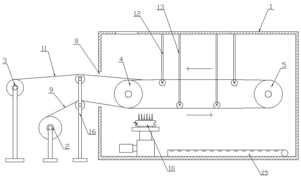
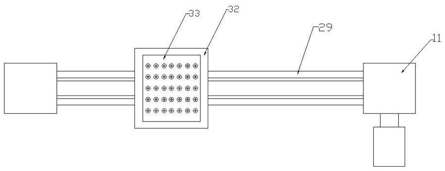
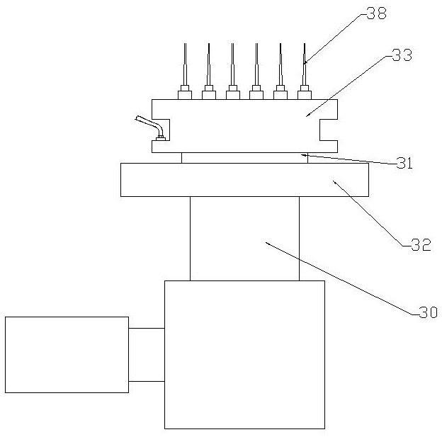
[0044] Embodiment 1: A kind of matrix multi-needle electrospinning equipment, see figure 1 , including an electrospinning chamber 1 , a feeding mechanism and a receiving mechanism arranged outside the electrospinning chamber 1 , and a transmission mechanism and a spinning mechanism 10 arranged in the electrospinning chamber 1 .

[0045] The feeding mechanism includes a feed roller 2 for installing the base material non-woven fabric 9 reel, and the receiving mechanism includes a receiving roller 3 for winding the finished material, and one end of the receiving roller 3 is connected with a receiving motor. It is used to drive the receiving roller 3 to rotate.

[0046] The transmission mechanism includes a driving roller 4, a driven roller 5 and a steel belt 6 set between the driving roller 4 and the driven roller 5. One end of the driving roller 4 is provided with a driving motor 7, and the output end of the driving motor 7 is connected to the driving roller 4. Coaxial connecti...

Embodiment 2

[0050] Embodiment 2: a matrix type multi-needle electrospinning equipment, the difference from Embodiment 1 is that an upper tension mechanism 12 and a lower tension mechanism 13 are also provided in the electrospinning chamber, and the upper tension mechanism 12 and The lower tensioning mechanism 13 all includes pull rods 14 vertically fixed on both sides of the top wall of the electrospinning chamber, and a tension roller 15 is installed between the two pull rods 14, see Figure 8 . The tension roller of the upper tension mechanism 12 passes between the upper steel belt and the lower steel belt, and is in close contact with the inner surface of the upper steel belt; the tension roller of the lower tension mechanism 13 passes through the upper steel belt. Pass between the belt and the lower side steel belt, and be in contact with the inner surface of the lower side steel belt; the upper tensioning mechanism 12 and the lower tensioning mechanism 13 are two groups.

[0051] An...

Embodiment 3

[0053] Embodiment 3: A matrix type multi-needle electrospinning equipment, the difference from Embodiment 2 is that a hot air pipeline is laid on the bottom surface of the electrospinning chamber 1 at the position behind the spinning mechanism, and the hot air pipe The road includes a hot-blast main pipe 24 connected to an external hot-air blower, and more than one hot-blast branch pipe 25 connected with the hot-blast main pipe 24. In this embodiment, three hot-blast branch pipes are provided, and the hot-blast branch pipe 25 is provided with cooling holes distributed equidistantly. 26. An air exhaust port 27 is provided on the top of the electrospinning chamber 1, and an exhaust fan is installed at the air exhaust port 27.

[0054] The working method of the matrix type multi-needle electrospinning equipment of the present invention is as follows: firstly, the reel of the base material non-woven fabric is installed on the feed roller, so that the movable end of the base materi...


PUM


Abstract

The invention discloses matrix type multi-needle electrostatic spinning equipment which comprises an electrospinning chamber, a feeding mechanism and a collecting mechanism arranged outside one side of the electrospinning chamber, and a conveying mechanism and a spinning mechanism arranged in the electrospinning chamber, wherein the conveying mechanism comprises a driving roller, a driven roller and a steel belt arranged between the driving roller and the driven roller in a sleeving mode; a movable end of a non-woven fabric base material on a feeding roller penetrates through a material passing channel, then bypasses the driven roller along the lower surface of the steel belt, comes out of the upper part of the material passing channel and is wound on the collecting roller; and a spinningmechanism is arranged below the steel belt close to one side of the driving roller and is used for spraying an electrostatic spinning raw material on the surface of the non-woven fabric base materialto form a nanofiber membrane layer. The electrostatic spinning device integrates the functions of feeding, spinning, drying and collecting; the integrated large electrostatic spinning equipment capable of achieving continuous production is formed; the conveying mechanism of the equipment is more stable, spinning is more uniform, and the automation degree and the production efficiency are higher.

Description

technical field [0001] The invention relates to the technical field of electrospinning, in particular to a matrix multi-needle electrospinning device. Background technique [0002] Electrospinning is a special fiber manufacturing process, which is a technology that jet-spins polymer solutions or melts in a strong electric field. Under the action of an electric field, the droplet at the nozzle will change from a spherical shape to a conical shape, and extend from the tip of the cone to form a fiber filament. This method can produce polymer filaments with nanometer diameters. Existing electrospinning generally uses relatively small equipment, which has low working efficiency and cannot achieve large-scale continuous production. For some technologies that need to form electrospun fiber membranes on the surface of the substrate, the mechanism for substrate transmission requires more High, to achieve the continuity and stability of substrate transmission, in order to ensure prod...

Claims


Application Information

Patent Timeline
Patent Type & Authority Applications(China)
IPC IPC(8): D01D5/00
CPCD01D5/0061D01D5/0069D01D5/0084
Inventor 杨永生琚河同李小要
Owner 河南曼博睿新材料科技有限公司
Learn More