Environment-friendly and energy-saving recovery device for boiler combustion boiler smoke gas

An environment-friendly, energy-saving, recovery device technology, which is applied in the direction of combustion methods, fixed tubular conduit components, tubular components, etc., can solve the problems of heat source waste, low recovery efficiency of furnace smoke, and low recovery efficiency.

Inactive Publication Date: 2021-02-09
周福明
View PDF0 Cites 3 Cited by
  • Summary
  • Abstract
  • Description
  • Claims
  • Application Information

AI Technical Summary

Problems solved by technology

However, the recovery efficiency of existing boiler flue gas waste heat recovery devices is not high, resulting in serious waste of heat sources. Therefore, the purpose of the present invention is an environmental protection and energy-saving recovery device for boiler combustion furnace flue gas to solve the problem of low recovery efficiency of furnace smoke

Method used


Image

  • Environment-friendly and energy-saving recovery device for boiler combustion boiler smoke gas
  • Environment-friendly and energy-saving recovery device for boiler combustion boiler smoke gas
  • Environment-friendly and energy-saving recovery device for boiler combustion boiler smoke gas

Examples


Embodiment 1

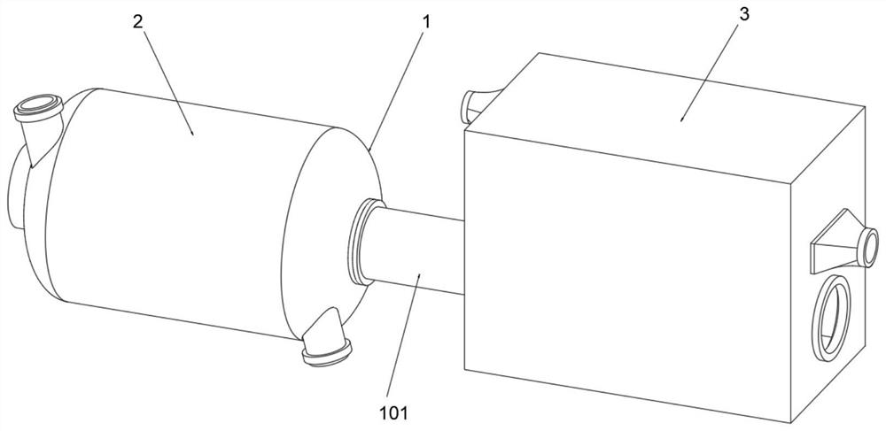
[0045] see Figure 1-Figure 11 As shown, the purpose of this embodiment is to provide an environmental protection and energy-saving recovery device for boiler combustion furnace flue gas, which includes a main body 1, a hot air circulation device 2 and a waste heat recovery device 3 installed on the main body 1;

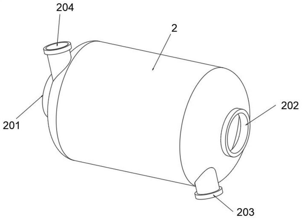
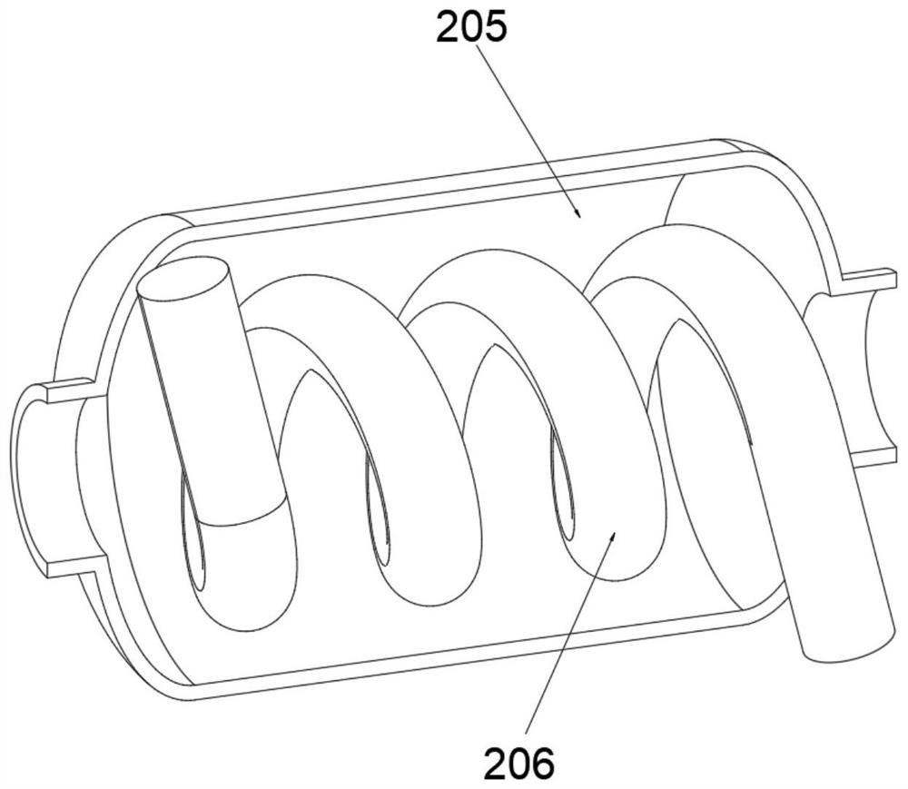
[0046] The hot air circulation device 2 at least includes: a first housing 207, an air inlet 201 is opened on the left side of the first housing 207, a cold air inlet 204 is provided on the side wall of the first housing 207 close to the top of the air inlet 201, The right side of the first housing 207 is provided with an air outlet 202, and the side wall of the first housing 207 is provided with a hot gas outlet 203 near the bottom of the air outlet 202. A heat exchange chamber 205 is provided in the first housing 207, and the heat exchange chamber 205 The upper baffle 2051 is fixedly connected to the top of the inner wall, the lower baffle 2052 is fixedly connected...


PUM


Abstract

The invention relates to the technical field of boiler combustion boiler smoke gas recovery, in particular to an environment-friendly and energy-saving recovery device for boiler combustion boiler smoke gas. The environment-friendly and energy-saving recovery device comprises a hot air circulation device, the hot air circulation device is internally provided with a first shell, an air inlet is formed in the left side of the first shell, a cold air inlet is formed in the position, close to the top of the air inlet, of the side wall of the first shell, a hot air outlet is formed in the position,close to the bottom of an air outlet, of the side wall of the first shell, a heat exchange cavity is formed in the first shell, the top of the inner wall of the heat exchange cavity is fixedly connected with an upper baffle plate, the bottom of the inner wall of the heat exchange cavity is fixedly connected with a lower baffle plate, an inner cavity of the heat exchange cavity is fixedly connected with a first heat pipe, and heat conduction fins are arranged. According to the environment-friendly and energy-saving recovery device, the arrangement of the heat conduction fins is conductive to increasing the heating surface and improving the heat transfer efficiency; and the heat conduction fins are provided with upper fin bodies and lower fin bodies, and air ducts formed by the upper fin bodies and the lower fin bodies, so that the effective contact areas between the high-temperature smoke gas and second heat pipes are further increased while an effect on guiding the smoke gas is achieved, and then the heat transfer efficiency is improved.

Description

technical field [0001] The invention relates to the technical field of flue gas recovery from boiler combustion furnaces, in particular to an environment-friendly and energy-saving recovery device for flue gas from boiler combustion furnaces. Background technique [0002] Boilers are smelting equipment widely used in many industries such as petroleum, chemical industry, metallurgy, machinery, etc. During their operation, due to the constraints of furnace structure, heat transfer principle, dew point corrosion and other factors, the exhaust gas temperature is generally high. The exhaust heat loss is often the largest item among the various losses of the heating furnace. The flue gas discharge takes away a lot of waste heat, which reduces the overall efficiency of the boiler. In order to improve the combustion efficiency of the boiler, the furnace smoke is usually recycled and reused to improve the energy conversion rate. [0003] The waste heat recovery of boiler combustion ...

Claims


Application Information

Patent Timeline
Patent Type & Authority Applications(China)
IPC IPC(8): F23L15/00F23J15/06F28D7/16F28F1/32F28F9/22
CPCF23J15/06F23L15/00F28D7/16F28F1/32F28F9/22F28F2009/224Y02E20/34
Inventor 周福明
Owner 周福明
Why Eureka
Try Eureka