Low-cost broadband millimeter wave array antenna
An array antenna, millimeter wave technology, applied in the direction of antenna, antenna coupling, antenna array, etc., to achieve the effect of wide impedance bandwidth, small size, and high power capacity
- Summary
- Abstract
- Description
- Claims
- Application Information
AI Technical Summary
Problems solved by technology
Method used
Image

Examples
Embodiment Construction
[0030] The present invention will be further described in detail below in conjunction with the embodiments and with reference to the accompanying drawings.
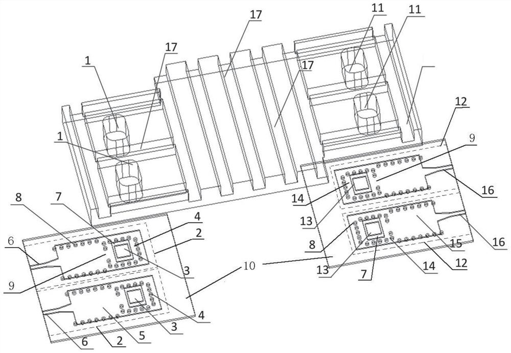
[0031] Embodiment 1 of the present invention is a low-cost broadband millimeter-wave array antenna, which mainly includes two parts: a metal horn part and a cavity-backed patch antenna.
[0032] Such as figure 1 As shown, the metal horn part includes at least two metal horn antenna units 1 for transmitting and two metal horn antenna units 11 for receiving, forming an array distribution. The metallic horn antenna unit 1 for transmitting and the metallic horn antenna unit 11 for receiving are identical in structure, and are realized by milling on the same piece of metal.
[0033]The cavity-backed patch antenna includes an antenna feeding dielectric plate 10, on which there are provided a transmitting feed unit 2 corresponding to the number of transmitting metal horn antenna units 1, and a corresponding number of receiving ...
PUM
| Property | Measurement | Unit |
|---|---|---|
| Length | aaaaa | aaaaa |
| Depth | aaaaa | aaaaa |
| Width | aaaaa | aaaaa |
Abstract
Description
Claims
Application Information
 - R&D
- Intellectual Property
- Life Sciences
- Materials
- Tech Scout
- Unparalleled Data Quality
- Higher Quality Content
- 60% Fewer Hallucinations
Browse by: Latest US Patents, China's latest patents, Technical Efficacy Thesaurus, Application Domain, Technology Topic, Popular Technical Reports.
© 2025 PatSnap. All rights reserved.Legal|Privacy policy|Modern Slavery Act Transparency Statement|Sitemap|About US| Contact US: help@patsnap.com