Single crystal furnace thermal field, control method thereof and single crystal furnace

A control method, technology of furnace heat field, applied to the control of single crystal furnace heat field, energy-saving single crystal furnace heat field, single crystal furnace field including the heat field, can solve low production efficiency and low output of single crystal furnace , High production cost and other issues, to achieve fast heating speed, reduce power fluctuation and ignition probability, reduce oxygen and impurities

Inactive Publication Date: 2021-02-23
XINTE ENERGY
View PDF11 Cites 1 Cited by
  • Summary
  • Abstract
  • Description
  • Claims
  • Application Information

AI Technical Summary

Problems solved by technology

[0005] In order to at least partially solve the technical problems of low output, low production efficiency and high p

Method used


Image

  • Single crystal furnace thermal field, control method thereof and single crystal furnace
  • Single crystal furnace thermal field, control method thereof and single crystal furnace
  • Single crystal furnace thermal field, control method thereof and single crystal furnace

Examples


Embodiment 1

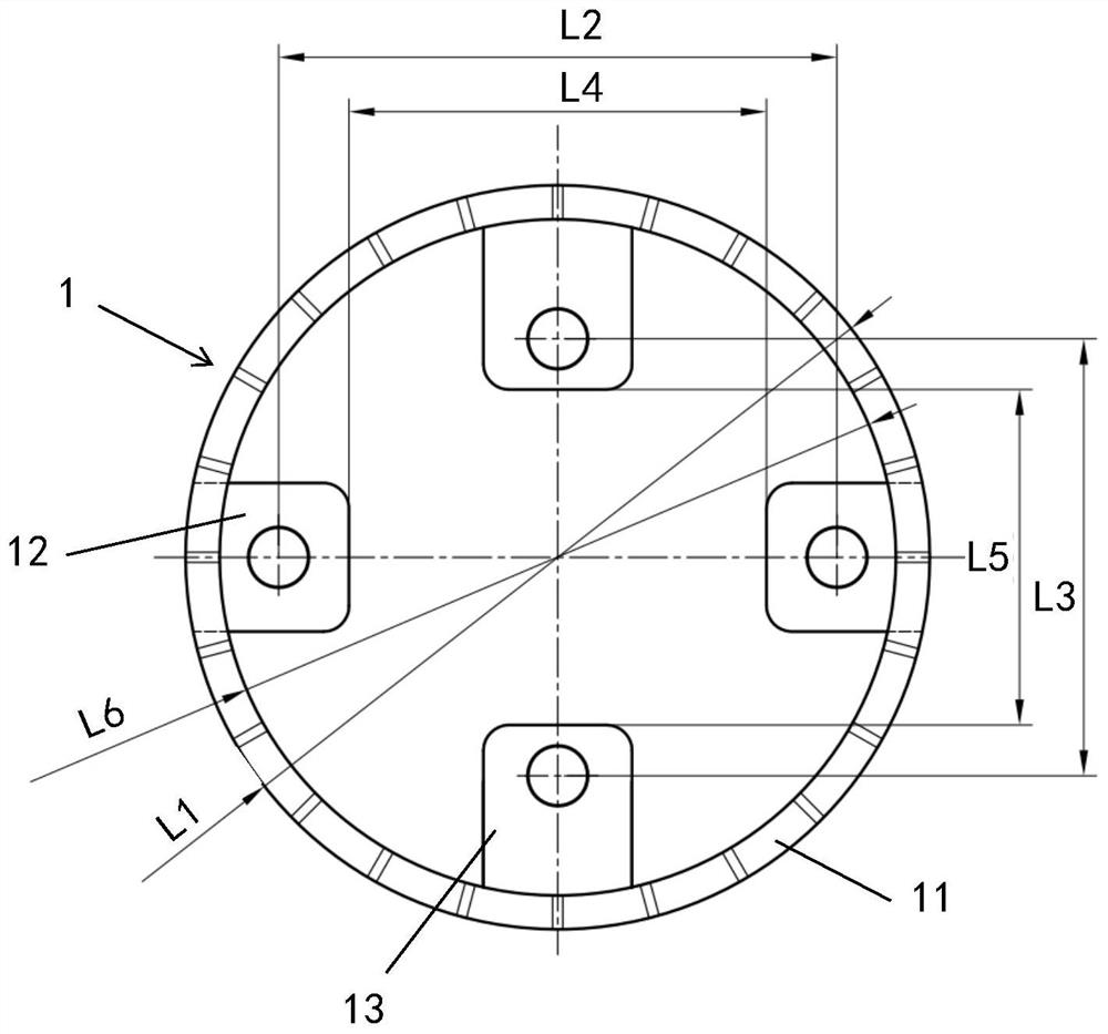
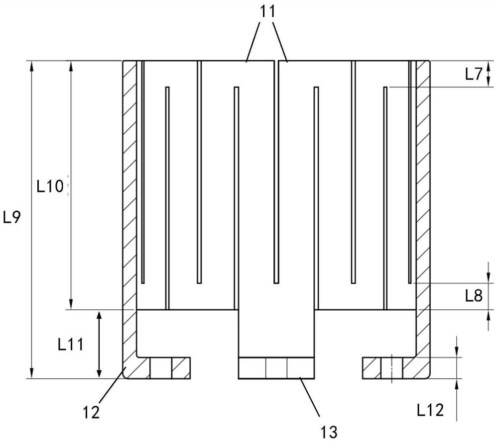
[0039]Such asfigure 1 withfigure 2 As shown, the present invention provides a single crystal furnace thermal field, including a heat preservation tube and a heater 1, the heater 1 is cylindrical, and the heat preservation tube is arranged on the periphery of the heater 1;

[0040]The diameter of the heater 1 is 710 to 740 mm, and the diameter of the heat preservation cylinder is 750 to 800 mm;

[0041]The distance between the upper edge of the heater 1 and the upper edge of the furnace barrel of the single crystal furnace is 63-67mm;

[0042]The bottom of the heater 1 is provided with two main electrode connection holes and two auxiliary electrode connection holes, the main electrode connection holes and the auxiliary electrode connection holes are alternately arranged along the circumference of the cylindrical heater, and the distance between the two main electrode connection holes It is 490-510mm, and the distance between the two secondary electrode connecting holes is 420-440mm.

[0043]The ...

Embodiment 2

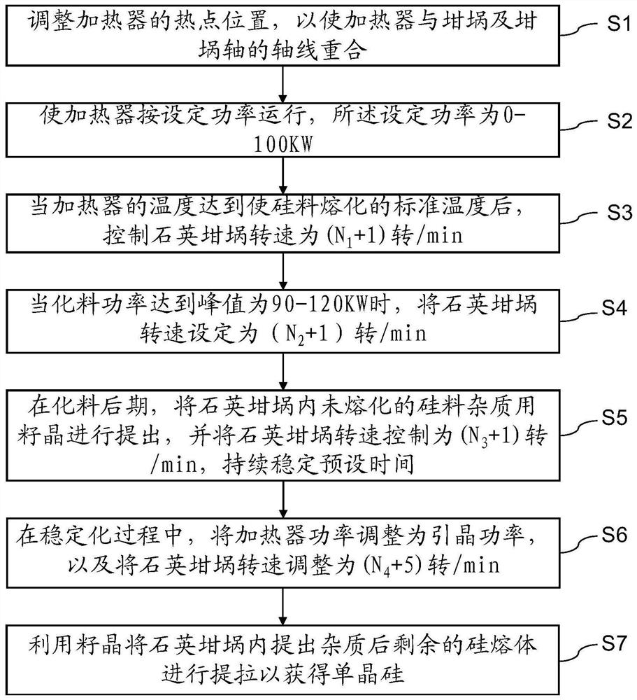
[0057]According to another aspect of the invention, such asimage 3As shown, the present invention also provides a single crystal furnace hot field control method for controlling the single crystal furnace hotfield as described above, including:

[0058]Step S1: Adjust the hotspot position of the heater to cause the heater to coincide with the axis of the crucible and the crucible;

[0059]Step S2: Make the heater to operate according to the set power, the set power of 0-100 kW;

[0060]Step S3: When the temperature of the heater reaches the standard temperature that is melted by the silicon, the quartz crucible rotation speed is (N)1+1) turn / min;

[0061]Step S4: When the chemical power reaches a peak of 90-120 kW, set the quartz crucible speed to (n2+1) turn / min;

[0062]Step S5: In the later period of the chemical, the unmelted silicon impurities in the quartz crucible were proposed, and the quartz crucible rotational speed was controlled (N3+1) turn / min, continuous stability preset time;

[...

Embodiment 3

[0090]On the other hand, the present invention also provides a single crystal furnace, which includes the above-mentioned single crystal furnace thermal field.

[0091]Further, the single crystal furnace further includes an auxiliary chamber, and an extension cavity is added to the upper part of the auxiliary chamber.

[0092]The addition of an extension cavity on the upper part of the sub-chamber increases the loading length of the sub-chamber crystal rods, and meets the design requirements for the use of silicon core crystal rods.


PUM

PropertyMeasurementUnit
Diameteraaaaaaaaaa
Diameteraaaaaaaaaa
Thicknessaaaaaaaaaa

Abstract

The invention provides a single crystal furnace thermal field, which comprises a heat preservation cylinder and a heater, the heat preservation cylinder is arranged on the periphery of the cylindricalheater, the diameter of the heater ranges from 710mm to 740mm, and the diameter of the heat preservation cylinder ranges from 750mm to 800mm; the distance between the upper edge of the heater and theupper edge of a furnace barrel of the single crystal furnace is 63-67mm; two main electrode connecting holes and two auxiliary electrode connecting holes are formed in the bottom of the heater, the main electrode connecting holes and the auxiliary electrode connecting holes are alternately formed in the circumferential direction of the cylindrical heater, the distance between the main electrode connecting holes is 490-510mm, and the distance between the auxiliary electrode connecting holes is 420-440mm. The invention also provides a corresponding thermal field control method and a single crystal furnace. According to the single crystal furnace thermal field, the control method thereof and the single crystal furnace, the existing single crystal furnace thermal field is modified, so that more materials are loaded in each production, the thermal field position and the production parameters are adjusted, the mounting fitting degree is improved, the heat stability is improved, the power fluctuation in the crystal pulling process is reduced, and oxygen and impurities generated by chemical reaction between a quartz crucible and silicon are reduced, and the product quality is improved.

Description


Claims


Application Information

Patent Timeline
Owner XINTE ENERGY
Why Eureka
Try Eureka