Production line waste cleaning system for food processing
A technology for food processing and production lines, applied in heating devices, grain processing, drying solid materials, etc., can solve problems such as sticking of device components, unfavorable device cleaning, etc., to achieve full coverage, promote water evaporation, and not easy to stick sticky effect
- Summary
- Abstract
- Description
- Claims
- Application Information
AI Technical Summary
Problems solved by technology
Method used
Image
Examples
Embodiment 1
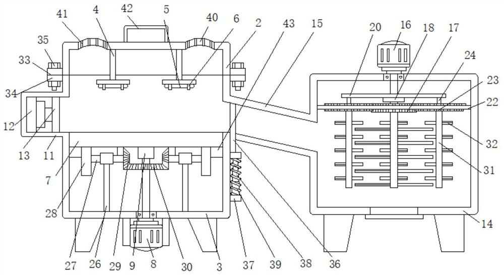
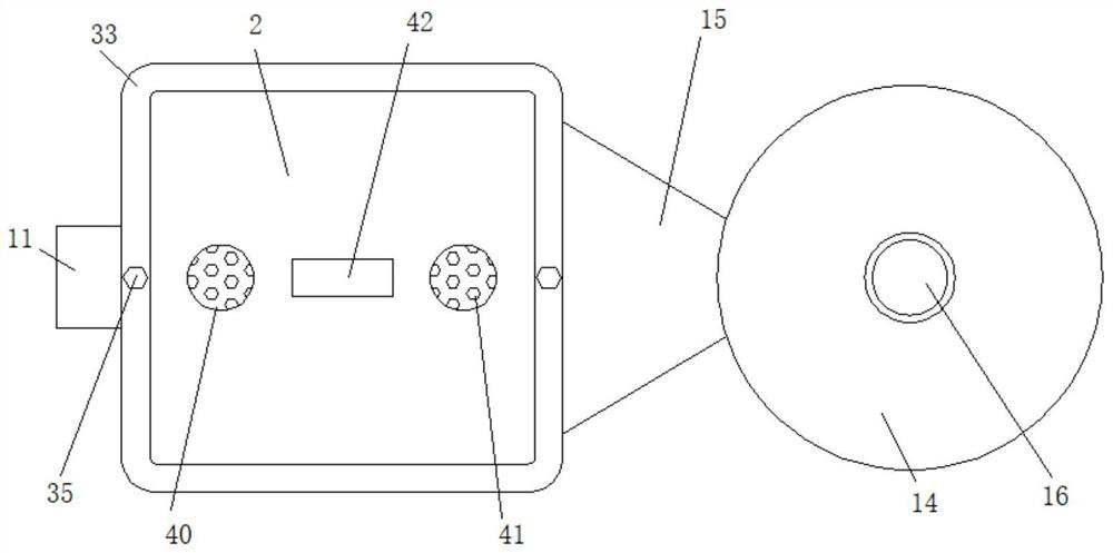
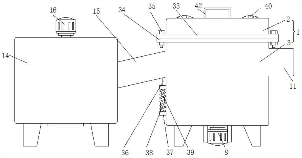
[0029] Embodiment one, such as Figure 1-7 As shown, a food processing production line waste cleaning system includes a drying box 1, the drying box 1 is square, the drying box 1 includes an upper shell 2 and a lower shell 3, and the top of the inner wall of the upper shell 2 is fixedly connected There are a plurality of T-shaped support frames 4, and heating pipes 5 are arranged under the plurality of support frames 4, and the plurality of heating pipes 5 are fixedly connected to the support frames 4 through the fixing frames 6 respectively, and a storage board is arranged horizontally in the lower casing 3 7. The storage plate 7 is circular, and the storage plate 7 is in contact with the inner wall of the lower casing 3, and the outer bottom surface of the lower casing 3 is fixedly connected with a first motor 8, and the shaft of the first motor 8 runs through the lower casing 3 and is connected to the lower casing 3. Active connection, the top of the shaft of the first moto...
Embodiment 2
[0030] Embodiment two, such as figure 1 , 6 As shown, the oscillating mechanism 10 includes a vertically arranged bracket 26, the bottom end of the bracket 26 is fixedly connected to the inner bottom surface of the lower housing 3, and the top end of the bracket 26 is rotatably connected to a horizontally arranged connecting shaft 27, and the connecting shaft 27 is away from the bottom of the first motor 8. One end of the shaft is fixedly connected with a cam 28, and the cam 28 is in contact with the bottom surface of the storage plate 7. The end of the connecting shaft 27 near the shaft of the first motor 8 is fixedly connected with a first cut gear 29, and the shaft of the first motor 8 is fixedly connected with a second gear. Cut gear 30, the first cut gear 29 is meshed with the second cut gear 30, the minimum radius of the cam 28 is greater than the radius of the first cut gear 29, and the diameter of the second cut gear 30 is greater than the length of the sliding plate 9, ...
Embodiment 3
[0031] Embodiment three, such as figure 1 , 5 As shown, the pulverizing mechanism 25 includes the pulverizing shaft 31 fixedly connected to the bottom surface of the driving gear 17 and the driven gear 23. A plurality of pulverizing shafts 31 are all vertically arranged, and a plurality of pulverizing shafts 31 are all fixedly connected with multiple cutting blades 32. The cutting blades 32 are all arranged horizontally, and the cutting blades on the driving gear 17 and the driven gear 23 are alternately arranged, and the food waste is cut and pulverized through the rotary cutting of a plurality of cutting blades 32, and the pulverizing shaft 31 on the driven gear 23 rotates by itself The revolution is carried out at the same time, so that the crushing effect covers more comprehensively and the crushing effect is better.
PUM
 Abstract
Description
Claims
Application Information
 - R&D
- Intellectual Property
- Life Sciences
- Materials
- Tech Scout
- Unparalleled Data Quality
- Higher Quality Content
- 60% Fewer Hallucinations
Browse by: Latest US Patents, China's latest patents, Technical Efficacy Thesaurus, Application Domain, Technology Topic, Popular Technical Reports.
© 2025 PatSnap. All rights reserved.Legal|Privacy policy|Modern Slavery Act Transparency Statement|Sitemap|About US| Contact US: help@patsnap.com


