
Infrared band-pass filtering structure and infrared band-pass filter using same

A band-pass filter and filter structure technology, applied in the field of infrared band-pass filter structure, can solve the problems of high production cost, low sputtering efficiency, and easy chipping of the film layer, so as to reduce resource costs, improve yield, and improve competition advantage effect

Pending Publication Date: 2021-03-09
KINGRAY TECH CO LTD
View PDF0 Cites 1 Cited by
  • Summary
  • Abstract
  • Description
  • Claims
  • Application Information

AI Technical Summary

Problems solved by technology

[0009] The main purpose of the present invention is to solve many problems such as the low sputtering efficiency of the well-known infrared bandpass filter, which leads to high production cost, and the warpage of the film layer leads to easy chipping during post-production cutting.

Method used

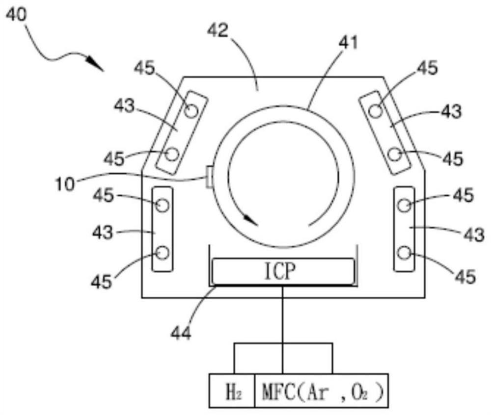
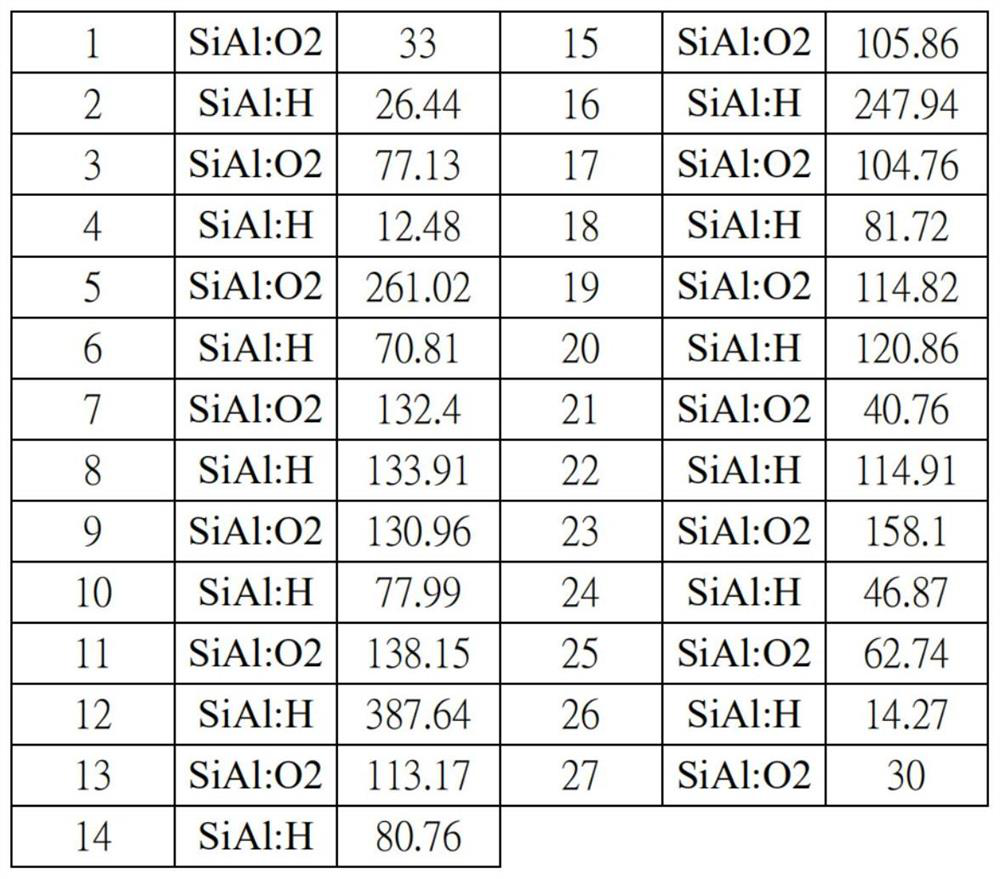

Image

  • Infrared band-pass filtering structure and infrared band-pass filter using same
  • Infrared band-pass filtering structure and infrared band-pass filter using same
  • Infrared band-pass filtering structure and infrared band-pass filter using same

Examples


Embodiment Construction

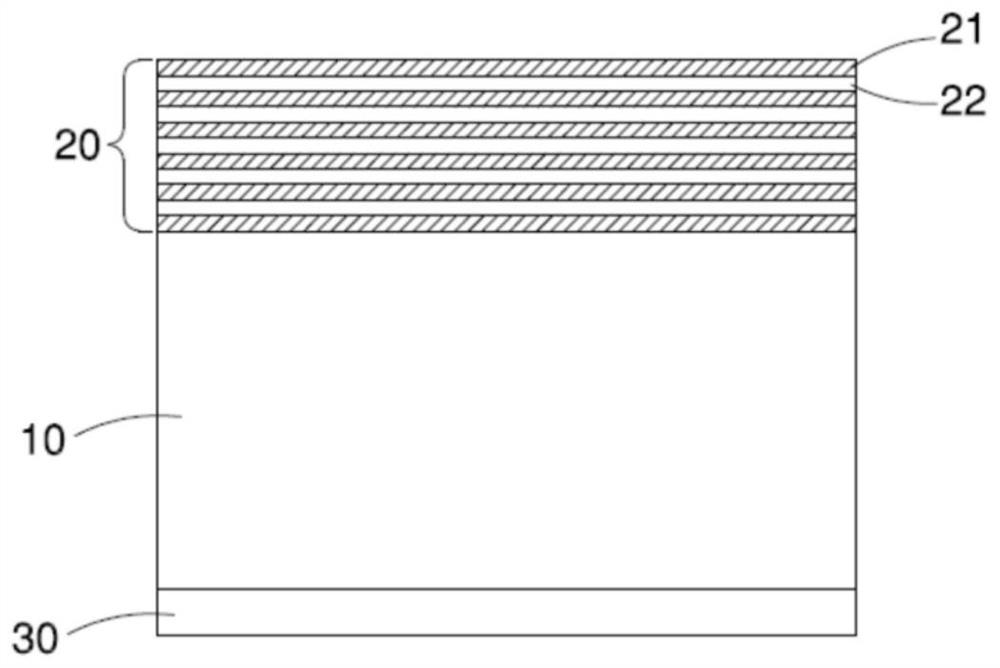
[0026] see figure 1 As shown, it is shown that the infrared bandpass filter of the present invention includes a substrate 10, an infrared bandpass filter structure 20 and an anti-reflection (AR) layer 30, wherein:

[0027] The substrate 10 is glass, and has a first side and a second side opposite to the first side.

[0028] The infrared bandpass filter structure 20 is formed on the first side of the substrate 10, and is formed by stacking multiple silicon aluminum hydride (SiAl:H) layers 21 and multiple lower refractive index layers 22 alternately, so that the infrared bandpass filter structure 20 Having a passband at least partially overlapping in the wavelength range from 800nm ​​to 1600nm, the passband having a central wavelength that varies in magnitude when the angle of incidence changes from 0° to 30° The magnitude of shifts is less than 11nm (about 10.3-10.5nm). Moreover, the infrared bandpass filter structure 20 has a thickness of 3000-5500nm, has a high OD value in ...


PUM

PropertyMeasurementUnit
Thicknessaaaaaaaaaa
Thicknessaaaaaaaaaa

Abstract

The invention provides an infrared band-pass filtering structure which is formed by alternately stacking a plurality of silicon aluminum hydride layers and a plurality of lower refractive index layers, the lower refractive index layers are oxide, the infrared band-pass filtering structure is provided with a passband which is at least partially overlapped within the wavelength range of 800 nm to 1600 nm, the passband is provided with a central wavelength, and the incident angle of the central wavelength is changed from 0 degree to 30 degrees, the magnitude deviation amplitude of the central wavelength is smaller than 11 nm; the infrared band-pass filter is characterized in that the infrared band-pass filtering structure is formed on a first side surface of a substrate, and an anti-reflection layer is formed on a second side surface, opposite to the first side surface, of the substrate; therefore, the sputtering efficiency can be improved, the manufacturing cost can be greatly reduced, the warping amount of the film layer can be reduced, and the problem that corners are prone to breakage during post-processing cutting is solved.

Description

technical field [0001] The invention relates to the technical field of an infrared band-pass filter structure and the structure of the filter, in particular to a method that can improve the sputtering efficiency to greatly reduce the production cost, and can reduce the warpage of the film layer to solve the problem of post-production cutting. The infrared band-pass filter structure for the problem of easy chipping and the infrared band-pass filter using the structure. Background technique [0002] General optical filters can be divided into band-pass filters, short-wave cut-off filters, and long-wave cut-off filters according to their spectral characteristics. Band-pass filter refers to the passage of light in a specific wavelength band, and the cut-off of light outside the pass band. It is divided into narrow band and broadband according to bandwidth. It is usually distinguished by the value of bandwidth to center wavelength. Less than 5% is narrow band, and greater than 5%...

Claims


Application Information

Patent Timeline
IPC IPC(8): G02B5/20G02B1/115
CPCG02B1/115G02B5/208
Inventor 邹政兴郑暐皞倪培元
Owner KINGRAY TECH CO LTD
Learn More