
Earth pressure balance shield foam system, working method and calculation method

An earth pressure balance shield and foam technology, which is applied in the fields of mixing methods, earthwork drilling, chemical instruments and methods, etc., can solve the problems of earth pressure balance shield tunneling spurts, different calculation methods, and large gas volume, etc. Novel method, clear control logic and reasonable working process

Pending Publication Date: 2021-03-12
POWERCHINA RAILWAY CONSTR +2
View PDF0 Cites 2 Cited by
  • Summary
  • Abstract
  • Description
  • Claims
  • Application Information

AI Technical Summary

Problems solved by technology

However, in the semi-automatic foam injection mode, the calculation methods for setting the gas volume in the foam system are different for each shield manufacturer, and no consensus can be reached
After some shield foam system parameters are set, the calculated gas volume is very large, resulting in adverse consequences such as gushing and over square in earth pressure balance shield tunneling

Method used


Image

  • Earth pressure balance shield foam system, working method and calculation method
  • Earth pressure balance shield foam system, working method and calculation method
  • Earth pressure balance shield foam system, working method and calculation method

Examples


Embodiment 1

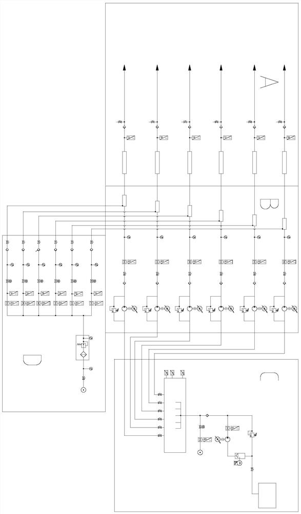
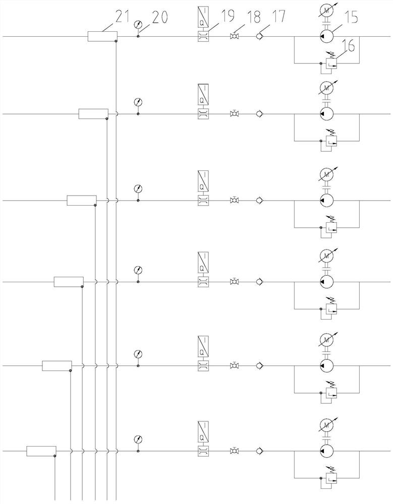
[0053] Such as Figure 1-Figure 5 As shown, the earth pressure balance shield foam system includes a solution generation unit and a gas transmission unit, the output pipes of the solution generation unit and the gas transmission unit are connected to the foam generator 21, and the foam generator 21 is used to provide muck improvement required foam;

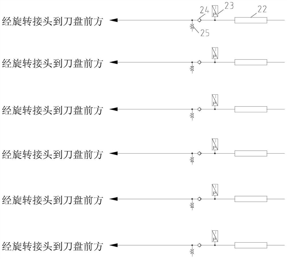
[0054] The foam generator 21 is connected to the foam pipeline, and the foam in the foam pipeline needs to be able to be sprayed to the front of the cutter head; further, the foam in the foam pipeline is directly and evenly sprayed to the front of the cutter head through the rotary joint, the pipeline and multiple nozzles in front of the cutter head On the palm surface, the muck cut by the cutter head is improved; the improved muck enters the soil cabin through the opening of the cutter head, and finally is output by the screw conveyor.

[0055] The solution generating unit comprises a container for containing the stock solution ...

Embodiment 2

[0058] In order to better realize storage, the container for containing the foam agent stock solution is a storage tank 1, and the bottom of the storage tank 1 is connected with the stock solution pipeline. The connection position between the stock solution pipeline and the storage tank 1 can make all the stock solution in the storage tank 1 flow out under the action of gravity. The installation position of the storage tank 1 is higher than the installation position of the first variable frequency screw pump 4 . The installation position of the mixing box 10 is higher than that of the second variable frequency screw pump 15 . Set up so that liquid flows by gravity to the variable frequency screw pump inlet.

Embodiment 3

[0060] The stock solution pipeline includes four sections, the four sections are respectively the first stock solution section, the second stock solution section, the third stock solution section and the fourth stock solution section; the second stock solution section and the third stock solution section are arranged between the first stock solution section and the fourth stock solution section. Between the stock solution pipe sections, the second stock solution pipe section and the third stock solution pipe section are arranged in parallel.

[0061] The second raw liquid pipe section is set as an overflow section, and a first safety overflow valve 5 is installed on the second raw liquid pipe section. The first safety overflow valve 5 can ensure the normal operation of the raw liquid pipeline and avoid damage to the first variable frequency screw pump 4 due to excessive pressure. When the outlet pressure of the first variable frequency screw pump 4 exceeds the safety pressure ...


PUM


Abstract

The invention discloses an earth pressure balance shield foam system, and the system comprises a solution generation unit and a gas transmission unit; output pipelines of the solution generation unitand the gas transmission unit are both connected to a foam generator, and foam required by earth pressure balance shield muck improvement is generated in the foam generator. The system is reasonable in structure, and normal operation of the system is guaranteed through the overflow section. Solution and gas are divided into two paths to enter the foam generator, a solution branch is provided witha mixing box to guarantee sufficient mixing of stock solution and water, and a gas path is provided with a condenser and a pressure reducing valve to guarantee safety of the gas path. The whole systemis reasonable in working process and clear in control logic, and safe and normal operation of the system is guaranteed. And a gas pressure sensor is arranged between the electric switch and the gas flow sensor. The calculation method mainly aims at a semi-automatic mode and a full-automatic mode, the calculation method of the two injection modes is novel, the calculated gas amount is reasonable and accurate, and a guarantee is provided for normal operation of the system.

Description

technical field [0001] The invention relates to earth pressure balance shield construction, in particular to an earth pressure balance shield foam system, working method and calculation method. Background technique [0002] With its advantages of safety, reliability, speed, economy, and environmental protection, the shield method is widely used in subways in major cities. Earth pressure balance shields are increasingly used in the construction of urban subway tunnels. [0003] Earth pressure balance shield muck improvement plays a very important role in shield construction. At present, the improvement materials of muck mainly include foam, bentonite mud, polymer aqueous solution and water. Due to the advantages of high foaming rate, good lubricity, low cost, and convenient operation, foam plays an important role in earth pressure balance shield muck soil improvement, and is widely used in silt formations, mudstone formations, sand formations and sandy pebble formations in...

Claims


Application Information

Patent Timeline
Patent Type & Authority Applications(China)
IPC IPC(8): B01F3/04B01F13/04B01F15/04B01F15/00E21D9/06B01F35/60
CPCE21D9/0685B01F23/235B01F35/602B01F35/21112B01F35/2113B01F35/883
Inventor 王国义蒋岿松任国庆杨平李宁张建明刘秀争胡秋芳
Owner POWERCHINA RAILWAY CONSTR
Learn More