

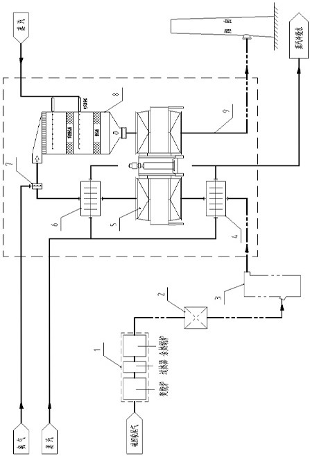
Device and a method for process for removing nitric oxide from tail gas of sulfur recovery device
A nitrogen oxide and sulfur recovery technology, applied in chemical instruments and methods, combustion methods, separation methods, etc., can solve problems such as catalyst poisoning and blockage, and achieve the effect of reducing costs and increasing operating life.
- Summary
- Abstract
- Description
- Claims
- Application Information
AI Technical Summary
Problems solved by technology
Method used
Image

Examples
specific Embodiment
[0057] The denitrification technology used in the patent of this invention is selective catalytic reduction (SCR).
[0058] Selective Catalytic Reduction (SCR), the first is to mix ammonia with dilution air or flue gas, generally diluted to 3-5% (volume fraction), and finally spray it into the flue gas upstream of the SCR reactor using the ammonia injection grid In the process, under the action of catalyst, ammonia selectively converts NOx (mainly NO and NO 2 , where NO dominates) into nitrogen and water, rather than by O 2 oxidized, reducing the NH 3 consumption.
[0059] The main reactions are as follows:
[0060] 4NH 3 +4NO+O 2 =4N 2 +6H 2 o
[0061] 4NH 3 +2NO 2 +O 2 =3N 2 +6H 2 O.
[0062] In the absence of catalysts, the above chemical reactions can only be carried out in a narrow temperature range (about 980°C). When different catalysts are selected, the reaction temperature can be controlled in different temperature ranges. Commercial denitrification cat...
Embodiment 1
[0065] A coal-to-oil enterprise sulfur recovery tail gas incineration tail gas, the flue gas conditions after heat recovery by waste heat boiler are as follows:
[0066] serial number project unit data Remark 1 temperature ℃ 220 2 pressure KPa (g) ≮7 3 volume flow N m 3 / h
152000 Standard state, wet basis, actual oxygen 4 SO 2
mg / Nm 3
9300 Standard state, dry basis, 3% oxygen 5 NOx mg / Nm 3
160 Standard state, dry basis, 3% oxygen 6 dust mg / Nm 3
trace 7 SO 3
ppm trace 8 h 2 S
ppm trace
[0067] The desulfurization temperature of the incineration tail gas is too high, and the natural air (152000Nm 3 / h, 10°C) mixed air cooling down to 134°C, SO 2 , NOx conversion concentration unchanged. Desulfurization adopts ammonia desulfurization process, and SO after ammonia desulfurization 2 Concentration down to 35mg / Nm 3 (Standard state, dry basis...
PUM
 Abstract
Description
Claims
Application Information