Defibrillation energy storage capacitor and charging circuit

An energy storage capacitor and charging circuit technology, applied in the field of medical devices, can solve the problems of wasting battery energy and missing the golden moment of rescuing patients, and achieve the effects of low equivalent resistance, good self-sealing characteristics, and good pulse resistance performance

Inactive Publication Date: 2021-03-16
SHANGHAI UNIV OF MEDICINE & HEALTH SCI
View PDF4 Cites 0 Cited by
  • Summary
  • Abstract
  • Description
  • Claims
  • Application Information

AI Technical Summary

Problems solved by technology

This will not only miss the golden moment of rescuing the patient, but also waste the energy in the battery

Method used


Image

  • Defibrillation energy storage capacitor and charging circuit
  • Defibrillation energy storage capacitor and charging circuit

Examples


Embodiment Construction

[0023] The present invention will be further described below in conjunction with the accompanying drawings and specific embodiments.

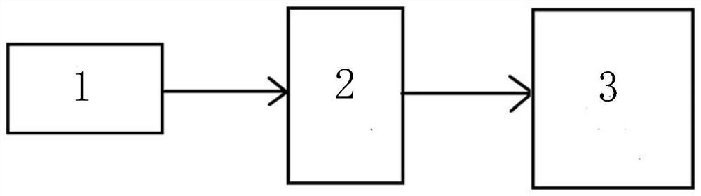
[0024] A defibrillation energy storage capacitor and charging circuit, comprising:

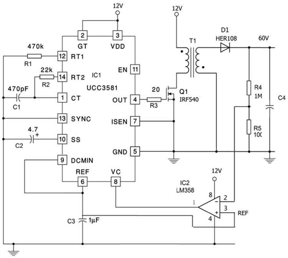
[0025] The battery 1 is connected to the charging circuit 2 and the low-voltage energy storage capacitor 3 in sequence; the first interface of the PWM chip IC1 of the charging circuit 2, the resistor R2, and the 14th interface of IC1 are connected in series, and the first interface of the IC1, the capacitor C1, Resistor R1 and the 12th interface of IC1 are connected in series, one way between the C1 and R1 is connected to the 13th interface of IC1, one way is connected to the capacitor C2 and then connected to the 10th interface of IC1, and one way is grounded, and the 9th interface of IC1 is connected to IC1 The 6th interface of the IC1 is connected to the capacitor C3 and then grounded, and the 8th interface of the IC1 is connected to the 1st interface of the...


PUM


Abstract

The invention relates to a defibrillation energy storage capacitor and a charging circuit. A storage battery is sequentially connected with the charging circuit and a low-voltage energy storage capacitor. A first interface of a PWM chip IC1 of the charging circuit, a resistor R2 and a fourteenth interface of the IC1 are connected in series. A first interface of the IC1, the capacitor C1, the resistor R1 and a twelfth interface of the IC1 are connected in series; one path between the C1 and the R1 is connected with a 13th interface of the IC1; one path is connected with a capacitor C2 and thenconnected with a tenth interface of the IC1, and the other path is grounded; one path of a ninth interface of the IC1 is connected with a sixth interface of the IC1, one path is grounded after being connected with a capacitor C3, and one path is connected with a third interface of the dual operational amplifier IC2; an eighth interface of the IC1 is connected with a first interface of the IC2, a fourth interface of the IC2 is grounded, the eighth interface of the IC2 is connected with 12V, the fourth interface of the IC2 is respectively connected with the resistor R4 and the resistor R5, and afifth interface of the IC1 is connected with a seventh interface of the IC1 in series. Safety is guaranteed, waiting is not needed, stable and repeated charging and discharging can be achieved, the economic effect is good, and power consumption is reduced.

Description

technical field [0001] The invention relates to the technical field of medical devices, in particular to a defibrillation energy storage capacitor and a charging circuit that ensure safety, do not need to wait, can be repeatedly charged and discharged stably, have good economic effects, and reduce power consumption. Background technique [0002] The defibrillator uses a large pulse current to act on the heart to eliminate arrhythmia and restore the heart to sinus rhythm. It has the advantages of high curative effect, fast action, and easy operation. Since the end of 1962, Bernard Lawn invented the DC defibrillator and successfully used it clinically, and this DC defibrillation method has been used until now. In order to achieve a large current output, the high-voltage energy storage capacitor is first charged with a DC current, and after reaching a higher voltage, it is quickly discharged through the electrodes on the patient's chest. This method has been used until now. ...

Claims


Application Information

Patent Timeline
IPC IPC(8): H02J7/34H02J7/00A61N1/39
CPCA61N1/3975A61N1/3981H02J7/00H02J7/345H02J7/342
Inventor 李萍高亚罕崔玉毛叶琼郭珊印张杏芳仲贝贝王惟
Owner SHANGHAI UNIV OF MEDICINE & HEALTH SCI
Why Eureka
Try Eureka