
Harmonic damping method and device for parallel capacitor bank

A capacitor bank and filter device technology, applied in harmonic reduction devices and AC networks to reduce harmonics/ripples, etc., can solve the problems of increased fundamental wave active power loss, cumbersome control procedures, damage to compensation equipment, etc. The effect of improving utilization efficiency, reducing technical difficulty, and reducing manufacturing costs

Active Publication Date: 2021-03-19
ELECTRIC POWER RESEARCH INSTITUTE OF STATE GRID SHANDONG ELECTRIC POWER COMPANY +1
View PDF8 Cites 1 Cited by
  • Summary
  • Abstract
  • Description
  • Claims
  • Application Information

AI Technical Summary

Problems solved by technology

[0003] The harmonics interact with the parallel capacitor bank. On the one hand, when the harmonic current is superimposed with the fundamental current flowing through the capacitor line, the effective value of the current flowing through the capacitor increases, which will inevitably increase the current thermal effect, resulting in an increase in the temperature of the parallel capacitor bank. shorten the service life; when the fundamental wave voltage and harmonic voltage are superimposed, the effective value of the voltage, especially the peak voltage, will increase significantly, and the capacitor will be broken down if the voltage is too high, which will seriously damage the compensation equipment; on the other hand, under the harmonic environment , the capacitive reactance value of the shunt capacitor decreases in multiples of harmonic times, and the equivalent reactance value of the power distribution network system side rises in multiples. In the face of a specific harmonic environment, the capacitor circuit may resonate in parallel with the equivalent reactance of the system, resulting in harmonics Further amplification of the current will not only damage electrical equipment such as capacitors, but also seriously threaten the safe and stable operation of the power system
[0004] In order to suppress the damage caused by the interaction between the parallel capacitor bank and the harmonics to the reliable operation of the compensation device and the system, a variety of harmonic suppression technologies are proposed. In the prior art, the series reactor method is often used to achieve the damping of different frequency harmonics Inhibition effect, in which the series reactance value depends on the harmonic content of the flow to the system side; and the passive filter branch formed with the capacitor usually adopts a single-tuned filter structure or a second-order high-pass filter structure, and the filter effect is better, but the active power of the fundamental wave The loss increases, and if a passive filter is used to suppress low-order harmonics, the required reactance rate is relatively large, so there are problems such as large fundamental reactive capacity loss, large reactor volume, and high cost; Source filtering technology detects the harmonic current flowing into the system side, and generates reverse compensation current by controlling fully-controlled components such as IGBTs, which can realize real-time tracking of harmonic current and dynamic compensation; however, the structure of the active filter is complex and the control process is cumbersome. Especially for the suppression of high-order harmonics, if the active filter is used for filtering, the operating frequency of the fully controllable device is required to increase, resulting in increased control difficulty, and the active filter is limited by its compensation capacity, and it is difficult to achieve complete harmonic compensation. , which has limitations in the application in engineering practice

Method used


Image

  • Harmonic damping method and device for parallel capacitor bank
  • Harmonic damping method and device for parallel capacitor bank
  • Harmonic damping method and device for parallel capacitor bank

Examples


Embodiment Construction

[0086] The application will be further described below in conjunction with the accompanying drawings. The following examples are only used to illustrate the technical solutions of the present invention more clearly, but not to limit the protection scope of the present application.

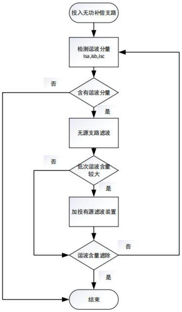
[0087] Such as figure 1 , the steps of the harmonic damping method for parallel capacitor banks are as follows:

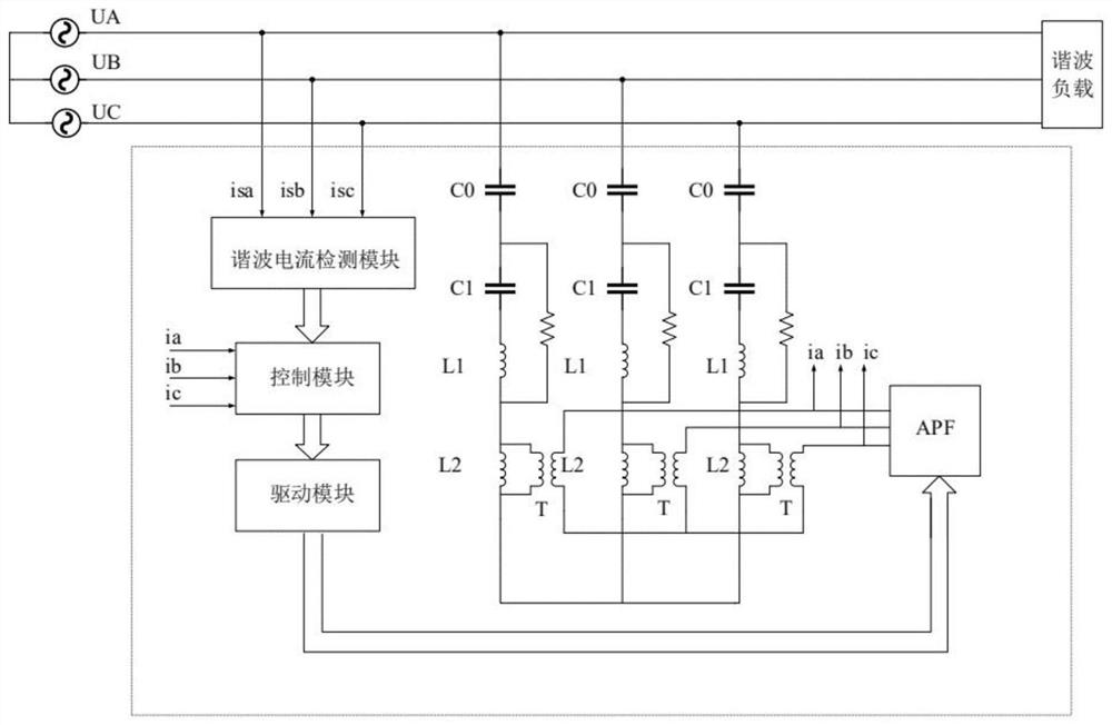
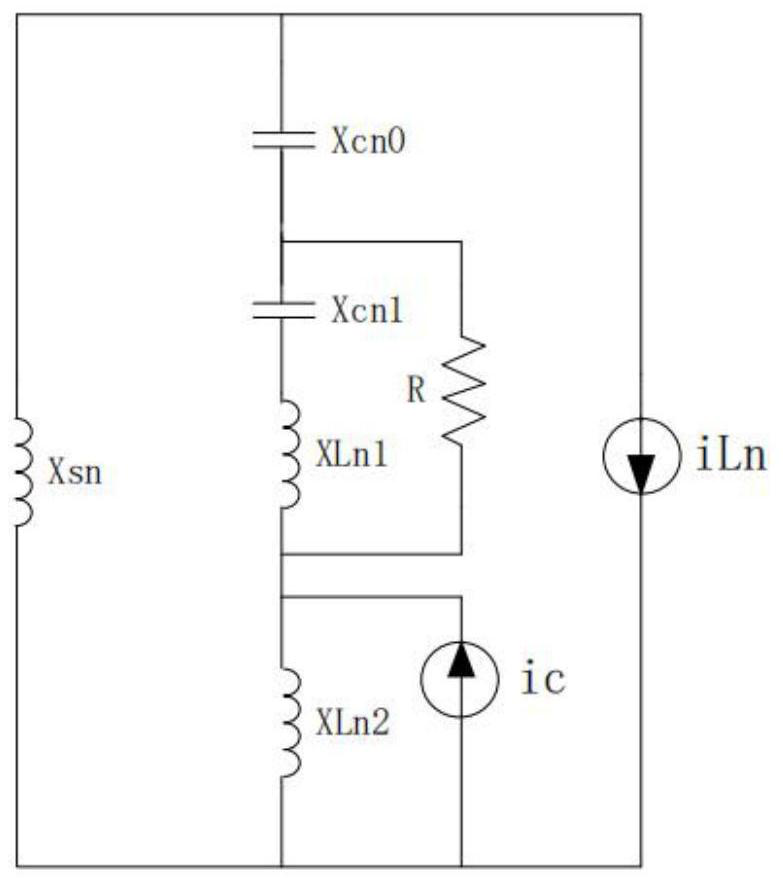
[0088] Step 1, collect the inductance value of the first inductance unit and the second inductance unit of the passive filtering device, and the series reactance rate of the parallel capacitor bank; based on the inductance value and the series reactance rate of the first inductance unit and the second inductance unit, the parallel The capacitor unit of the capacitor bank is divided into a reactive power compensation capacitor unit and a harmonic damping capacitor unit.

[0089] specifically,

[0090] In step 1, the reactive power compensation capacitor unit and the harmonic damping c...


PUM


Abstract

The invention relates to a harmonic damping method and device for a parallel capacitor bank, and the method comprises the steps: achieving the access of a passive filtering device through a part of parallel capacitor units in the parallel capacitor bank, and achieving the access of a low-voltage active filtering device to the passive filtering device through a transformer; employing the passive filtering device for suppressing higher harmonics, and employing the active filtering device for compensating lower harmonics, so that harmonic damping of the parallel capacitor bank is realized. Effective governance of high-order harmonics and low-order harmonics is achieved through a hybrid structure of the passive filtering device and the active filtering device, and the advantages of reduction of active loss, dynamic tracking of harmonic changes, large reactive capacity, wide damping frequency band and the like are achieved. And the harmonic suppression effect can be improved while the costof electrical equipment is reduced.

Description

technical field [0001] The invention belongs to the technical field of harmonic suppression in electric power systems, and more specifically relates to a harmonic damping method and device for parallel capacitor banks. Background technique [0002] In order to cope with the reactive power loss of long-distance transmission lines and inductive loads, and reduce the pressure on generator generating capacity, shunt capacitors are the most commonly used reactive power compensation devices in medium and low voltage power distribution devices. Switching parallel capacitor banks improves the power factor of the line, thereby increasing the power transmission capacity of the line and improving the voltage level of the busbar. The load types of the power grid are diverse. Energy-saving lamps, transformers, motors and other equipment are equipped with iron core coils. The saturation of the iron core presents nonlinear characteristics, which will generate harmonic currents; When conne...

Claims


Application Information

Patent Timeline
Patent Type & Authority Applications(China)
IPC IPC(8): H02J3/01
CPCH02J3/01Y02E40/40
Inventor 张岩于丹文苏永智张青青王庆玉王华佳张高峰
Owner ELECTRIC POWER RESEARCH INSTITUTE OF STATE GRID SHANDONG ELECTRIC POWER COMPANY
Learn More