Inductor and manufacturing method thereof

A technology of inductors and electrodes, applied in the field of inductors, can solve the problems of unfavorable large-scale production, increased equipment cost, high welding resistance, etc., and achieve the effects of avoiding high difficulty in coil winding, improving production efficiency, and strong ability to resist saturation current

Active Publication Date: 2021-04-09
SHENZHEN SUNWAY COMM
View PDF9 Cites 2 Cited by
  • Summary
  • Abstract
  • Description
  • Claims
  • Application Information

AI Technical Summary

Problems solved by technology

[0003] For the traditional one-piece inductor, the coil needs to be spot-welded on the material frame, the smaller size is difficult to fix, and it is prone to false welding, and the welding resistance is higher
[0004] In addition, for traditional one-piece inductors, the winding of the coil is usually single-channel winding, and increasing the output requires increasing equipment costs, which is not conducive to mass production

Method used


Image

  • Inductor and manufacturing method thereof
  • Inductor and manufacturing method thereof
  • Inductor and manufacturing method thereof

Examples


preparation example Construction

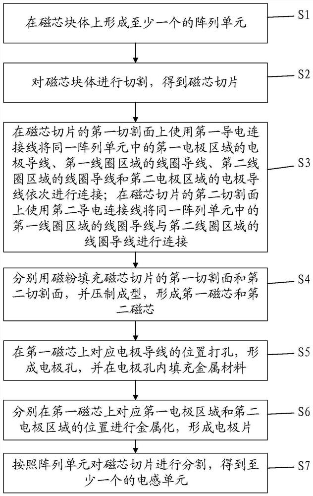
[0035] see figure 1 , a method for preparing an inductor, comprising:

[0036] (1) At least one array unit is formed on the magnetic core block, the array unit includes a first coil area and a second coil area that are oppositely arranged, and are respectively located on both sides of the first coil area and the second coil area The first electrode area and the second electrode area, the first coil area and the second coil area are respectively embedded with the same number of linearly arranged coil wires, and the first electrode area and the second electrode area are respectively embedded with an electrode wire, the coil wire and the electrode wire being parallel to each other;

[0037] (2) cutting the magnetic core block in a direction perpendicular to the length direction of the coil wire and the electrode wire to obtain a magnetic core slice;

[0038] (3) Use the first conductive connecting wire on the first cutting surface of the magnetic core slice to connect the elect...

Embodiment 1

[0059] Please refer to Figure 1-12 , Embodiment 1 of the present invention is: a preparation method of an inductor, which can be applied to the preparation of an integrally formed inductor, such as figure 1 shown, including the following steps:

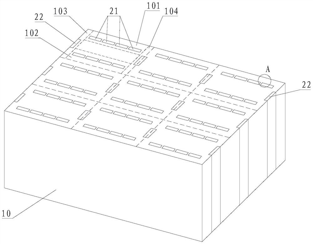
[0060] S1: At least one array unit is formed on the magnetic core block.

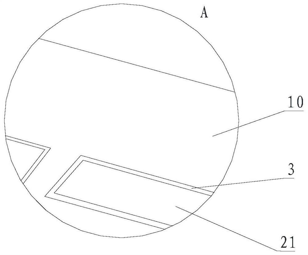
[0061] Such as figure 2 as shown, figure 2 Nine array units ( figure 2 9 parts of the same area divided by dotted lines), each array unit includes a first coil area 101 and a second coil area 102 that are oppositely arranged, and are respectively located in the first coil area 101 and the second coil area 102 The first electrode area 103 and the second electrode area 104 on both sides, the first coil area 101 and the second coil area 102 are respectively embedded with the same number of coil wires 21 arranged linearly, the first electrode area 103 and An electrode wire 22 is respectively embedded in the second electrode regions 104 , and the coil wire ...

Embodiment 2

[0085] This embodiment is a specific embodiment of the first embodiment.

[0086] In this embodiment, the material of the magnetic core block and the magnetic powder are FeSiCr alloy, the cross-sectional size of the coil wire is 0.2mm*0.04mm, the cross-sectional size of the electrode wire is 0.2mm*0.04mm, the material of the coil wire and the electrode wire They are all made of copper with an insulating layer on the surface; the area where the first conductive connecting wire and the second conductive connecting wire directly contact the coil wire and the electrode wire has no insulating layer, and other areas are attached with an insulating layer; the height of the magnetic core slice is 0.8 mm. The pressure of the pressing molding process used is 150MPa, and the temperature during pressing is 200°C. The metal material used to fill the electrode hole is a conductive paste. The conductive paste is a mixture of silver powder, copper powder and epoxy resin adhesive. The cross-se...


PUM

PropertyMeasurementUnit
widthaaaaaaaaaa
thicknessaaaaaaaaaa
widthaaaaaaaaaa

Abstract

The invention discloses an inductor and a manufacturing method thereof. The method comprises the following steps: forming at least one array unit on a magnetic core block, wherein coil wires which are the same in number and arranged linearly are embedded in two coil areas respectively, and electrode wires are embedded in two electrode areas respectively; cutting to obtain magnetic core slices; connecting the electrode leads of the two electrode areas and the coil leads of the two coil areas on the first cutting surface of the magnetic core slice by using a first conductive connecting wire; connecting the coil wires of the two coil areas on the second cutting surface of the magnetic core slice by using a second conductive connecting wire; respectively filling the first cutting surface and the second cutting surface with magnetic powder, and carrying out compression molding to form a first magnetic core and a second magnetic core; forming an electrode hole in the first magnetic core, and filling a metal material; forming an electrode plate on the first magnetic core; and segmenting the magnetic core slices according to the array units to obtain at least one inductance unit. The manufacturing method is beneficial to manufacturing of small-size inductors and batch production of inductance elements.

Description

technical field [0001] The invention relates to the technical field of inductors, in particular to an inductor and a preparation method thereof. Background technique [0002] With the rapid development of electronic products, high frequency, integration, and miniaturization are the trends of its technological development. Smartphones, notebooks and other products mostly use power management ICs to manage various functional modules in a unified manner, and power inductors play a role in reducing ripple current. The general requirements for power inductors are miniaturization, thinning, high frequency, low DCR, high current, low EMI (electromagnetic interference), and low manufacturing cost. The obvious advantage of the one-piece inductor is that it can withstand high current. In addition, the integrated inductor has lower loss and higher conversion efficiency, which can effectively improve the battery life of the mobile phone; the overall size of the integrated inductor is ...

Claims


Application Information

Patent Timeline
Patent Type & Authority Applications(China)
IPC IPC(8): H01F41/00H01F17/04H01F37/00
CPCH01F41/00H01F17/04H01F37/005
Inventor 刘开煌高鹏虞成城
Owner SHENZHEN SUNWAY COMM
Why Eureka
Try Eureka