
Cooling liquid treatment process for four-shaft grinding machine for machining of milling cutter

A technology for processing technology and coolant, applied in milling cutters, milling machine equipment, metal processing equipment, etc., can solve the problems of good impurity cleaning effect, increase filtration difficulty, and high degree of automation, and achieve good impurity cleaning effect, increase filtration difficulty, The effect of a high degree of automation

Inactive Publication Date: 2021-04-13
张达宇
View PDF0 Cites 1 Cited by
  • Summary
  • Abstract
  • Description
  • Claims
  • Application Information

AI Technical Summary

Problems solved by technology

[0005] The purpose of the present invention is to address the deficiencies of the prior art. By setting up the removal of impurities on the grinding station, the impurities adhering to the water can be collected in two parts, and then the impurities can be completely removed, even if the grinding work is completed. Finally, there is no need to clean the bearing mechanism every time. In addition, the sieve millstone particles and iron filings are used to screen the impurities collected on both sides, and the water, iron filings and millstone particles are classified at the same time. Output in time to avoid re-mixing with subsequent water and increase the difficulty of filtration. It has a high degree of automation and good impurity cleaning effect, thus solving the problem of material blockage and entrainment when the water flow is output downward due to the inability to discharge impurities in time. The output of impurities leads to the technical problem of the wear phenomenon of the workpiece when the accessories are polished.

Method used


Image

  • Cooling liquid treatment process for four-shaft grinding machine for machining of milling cutter
  • Cooling liquid treatment process for four-shaft grinding machine for machining of milling cutter
  • Cooling liquid treatment process for four-shaft grinding machine for machining of milling cutter

Examples


Embodiment 1

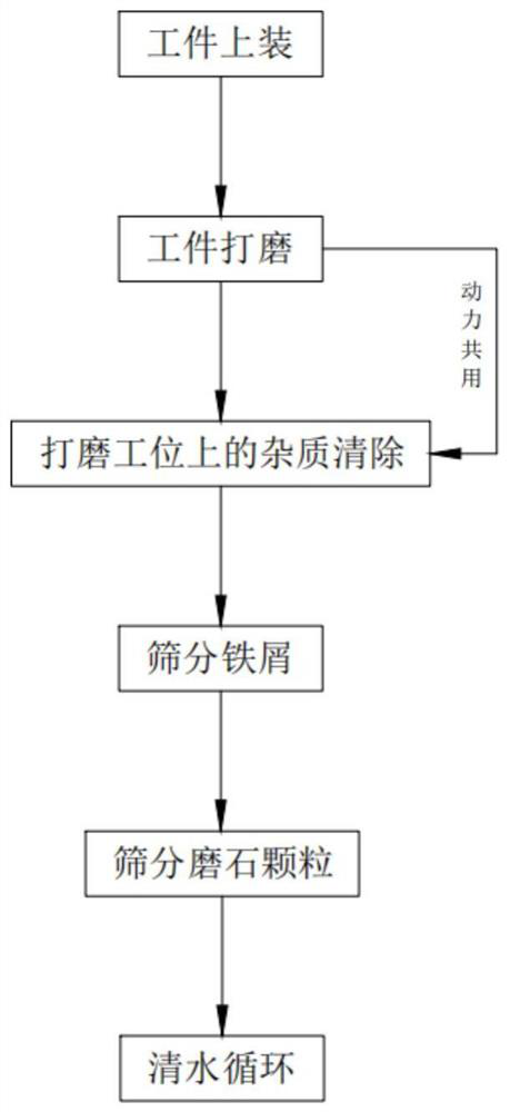
[0085] Such as figure 1 As shown, a coolant treatment process for a four-axis grinding machine for milling cutter processing, including:

[0086] Step 1, uploading the workpiece, first manually placing the workpiece on the workbench 44 of the carrying mechanism 4;

[0087] Step 2, the workpiece is polished, the grinding mechanism 2 is started, the grinding mechanism 2 completes the grinding work of the workpiece, and then the cooling mechanism 3 completes the cooling work of the grinding mechanism 2;

[0088] Step 3, removing impurities on the grinding station, synchronously with the step 2, when the support shaft 51 moves downward, the discharge plate 52 is set in communication with the drop hole a46 through the frame 41, so that the discharge plate 52 moves along the frame 41 to Move down, and then collect the impurities on the support plate 43; when the support shaft 51 moves upward, the discharge plate 52 is connected with the drop hole a46 through the frame 41, so that t...

Embodiment 2

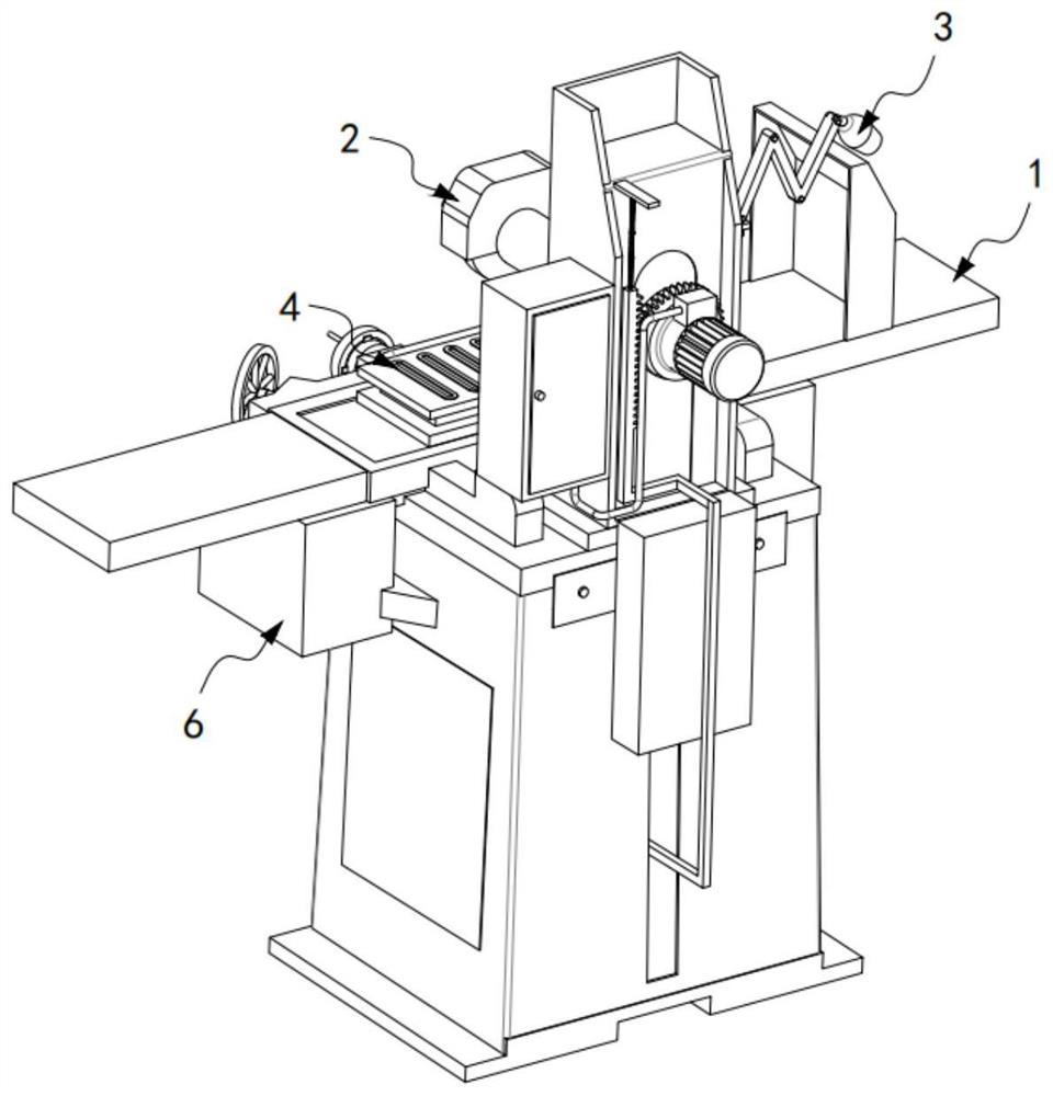
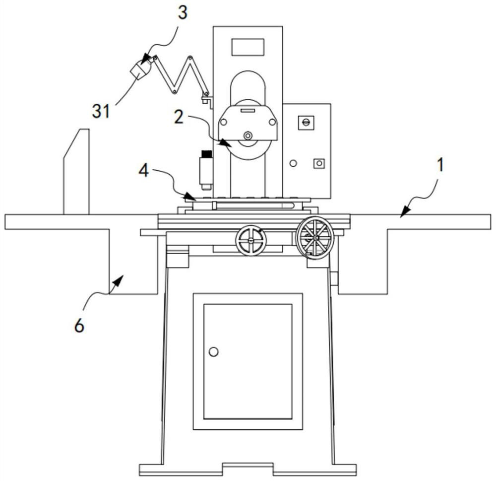
[0103] Such as Figure 2 to Figure 4 As shown, an automatic production device for CNC lathe accessories, including a grinding machine 1, a grinding mechanism 2 installed on the grinding machine 1, a cooling mechanism 3 arranged on one side of the grinding mechanism 2, and a cooling mechanism 3 installed on the grinding mechanism 2 The bearing mechanism 4 below and installed on the grinding machine 1, the adsorption mechanism 5 arranged below the bearing mechanism 4 and used to collect impurities on the bearing mechanism 4, and two groups are arranged symmetrically on the bearing mechanism 4. Screening mechanism 6 on both sides of mechanism 4;

[0104] The screening mechanism 6 includes an iron filings collection assembly 61, a millstone particle collection assembly 62 arranged below the iron filings collection assembly 61, and one end communicates with the grinding stone particle collection assembly 62 and the other end communicates with the cooling unit. Mechanism 3 communic...

Embodiment 3

[0151] Such as Figure 13 to Figure 15 As shown, the parts that are the same as or corresponding to those in the second embodiment are marked with the corresponding reference numerals in the second embodiment. For the sake of simplicity, only the differences from the second embodiment will be described below. The difference between this embodiment three and embodiment two is:

[0152] further, such as Figure 13 to Figure 15 As shown, the second transmission mechanism 8 includes:

[0153] The rotating member 81, the rotating member 81 includes a transmission gear 811 that is coaxial with the rotating shaft 613 and synchronously transmitted, and a transmission rack 812 that is meshed with the transmission gear 811 and fixedly connected with the connecting rod 73; and

[0154] The translation member 82, the translation member 82 includes a drive gear 821 coaxial with the transmission gear 811 and synchronously transmitted, a drive rack 822 meshed with the drive gear 821 and ar...


PUM


Abstract

The invention relates to a cooling liquid treatment process for a four-shaft grinding machine for machining of a milling cutter. The cooling liquid treatment process includes the following steps of: step 1, loading a workpiece, namely firstly manually placing the workpiece on a workbench of a bearing mechanism; step 2, polishing the workpiece; step 3, removing impurities at a grinding station during the step 2; step 4, screening iron scraps; step 5, screening millstone particles; and step 6, circulating clear water, putting the clear water on the lower layer of a collecting basket into a water collecting frame, and finally allowing water flow in the water collecting frame to enter a cooling mechanism through a connecting pipe of a circulating assembly under the action of a water pump so as to be repeatedly used. The cooling liquid treatment process provided by the invention solves the technical problems that due to the fact that impurities cannot be discharged in time, blockage of discharged materials is likely to occur, and when water flow is output downwards, impurities are output with the water flow, and accordingly a workpiece is abraded when accessories are ground and machined.

Description

technical field [0001] The invention relates to the technical field of four-axis grinding machines, in particular to a coolant treatment process for four-axis grinding machines used for milling cutter processing. Background technique [0002] CNC tool grinding machines are used to process end mills, ball end mills, step drills, reamers, forming mills, deep hole drills, triangular chisels and planer tools, etc., and can sharpen the edges and grooves of metal cutting tools And the outer circle, plane and complex shape of general medium and small parts. In the actual use process, in order to realize the processing of complex shapes and the grinding of various angles of various tools, multi-coordinate control must be adopted. Therefore, the four-axis Linkage CNC tool grinding machines are widely used. Grinding is the final process of mechanical processing, which has a direct impact on the precision, performance and service life of the finished product. During the processing, th...

Claims


Application Information

Patent Timeline
IPC IPC(8): B24B3/02B24B55/03B24B55/12B24B41/06B07B1/04B07B1/08B07B7/06B07B9/02B03C1/26
CPCB03C1/26B07B1/04B07B1/08B07B7/06B07B9/02B24B3/02B24B41/06B24B55/03B24B55/12
Inventor 张达宇
Owner 张达宇
Learn More