
New energy automobile charging pile based on smart city

A new energy vehicle, intelligent charging technology, applied in electric vehicle charging technology, charging stations, electric vehicles, etc., can solve the problems of accelerating the aging rate of charging piles, shortening the service life of the device, and being susceptible to rain erosion, so as to delay aging. The effect of speed, damage reduction, and practical safety improvement

Inactive Publication Date: 2021-04-13
李志超
View PDF0 Cites 1 Cited by
  • Summary
  • Abstract
  • Description
  • Claims
  • Application Information

AI Technical Summary

Problems solved by technology

[0003] The existing charging piles for new energy vehicles still have some deficiencies in the actual application process. For example, most of the existing charging piles are installed in the open air. The outside world is easily eroded by rainwater, resulting in short-circuit damage to the line. At the same time, the body of the charging pile installed in the open air is eroded by sunlight and rainwater, which accelerates the aging rate of the charging pile and shortens the service life of the device.

Method used


Image

  • New energy automobile charging pile based on smart city
  • New energy automobile charging pile based on smart city
  • New energy automobile charging pile based on smart city

Examples


Embodiment Construction

[0025] The following will clearly and completely describe the technical solutions in the embodiments of the present invention with reference to the accompanying drawings in the embodiments of the present invention. Obviously, the described embodiments are only some, not all, embodiments of the present invention. Based on the embodiments of the present invention, all other embodiments obtained by persons of ordinary skill in the art without making creative efforts belong to the protection scope of the present invention.

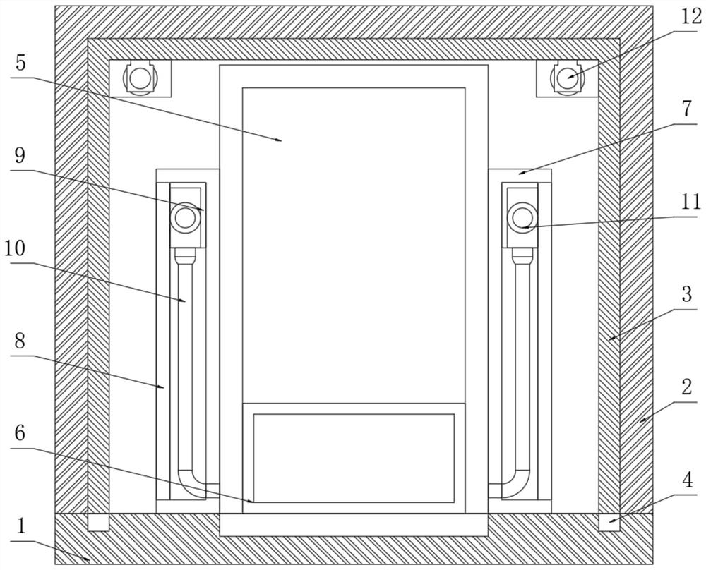
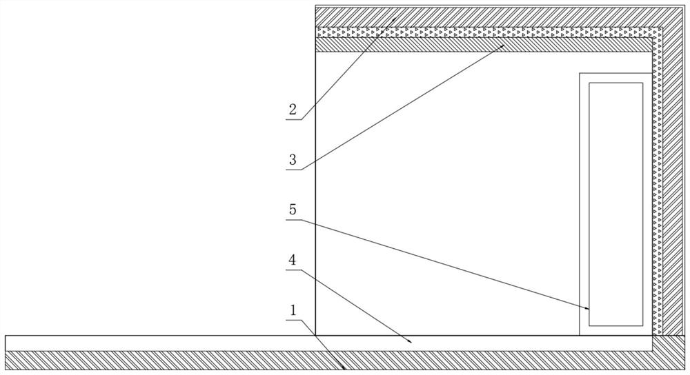
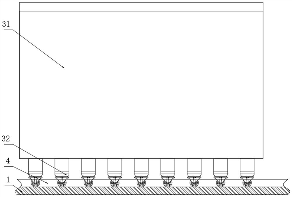
[0026] as attached Figure 1-7 A charging pile for new energy vehicles based on a smart city is shown, including a plastic insulating base 1, a roof 2 is fixedly installed on the top surface of the plastic insulating base 1, and the interior of the roof 2 is movably socketed with the plastic insulating base 1 The top surface of the movable telescopic shed 3 is movably connected, and the bottom ends of the left and right side walls of the movable telescopic she...


PUM


Abstract

The invention discloses a new energy vehicle charging pile based on a smart city, and particularly relates to the technical field of smart cities. The charging pile comprises a plastic insulation base, a shed is fixedly installed on the top surface of the plastic insulation base, a movable telescopic shed body movably connected with the top surface of the plastic insulation base is movably sleeved in the shed, and the bottom ends of the left side wall and the right side wall of the movable telescopic shed body are movably connected with limiting sliding grooves formed in the top face of the plastic insulation base in an embedded mode. According to the new energy vehicle charging pile, through arrangement of the shed and the movable telescopic shed body, in the working process of the charging pile, the sliding shed and the shed are movably connected into a whole through cooperation of electric hydraulic rods, two limiting sliding grooves and two sets of limiting pulleys, and a Dike aluminum foil heat insulation coiled material arranged on the outer surface of the shed is used for being matched with an aerogel felt arranged on the inner wall of the shed to isolate light radiation heat in a double-layer mode, so that the damage degree of outdoor high temperature to an intelligent charging unit is reduced, the aging rate of the intelligent charging unit is delayed, and the service life of the charging pile is prolonged.

Description

technical field [0001] The invention relates to the technical field of smart cities, and more specifically, the invention relates to a charging pile for new energy vehicles based on smart cities. Background technique [0002] The charging pile is a fuel dispenser with a function similar to that in a gas station. It can be fixed on the ground or wall and installed in public buildings, such as public buildings, shopping malls, public parking lots and parking lots or charging stations in residential areas. The voltage level is the power equipment for charging various types of new energy electric vehicles; the input end of the charging pile is directly connected to the AC power grid, and the output end is equipped with a charging plug for charging electric vehicles; the charging pile generally provides conventional charging and There are two charging methods of fast charging. People can use a specific charging card to swipe the card on the human-computer interaction interface pr...

Claims


Application Information

Patent Timeline
Patent Type & Authority Applications(China)
IPC IPC(8): E04H6/02E04H6/04H02B1/28H02B1/30H02B1/32H02B1/56B60L53/16B60L53/18B60L53/31
CPCB60L53/16B60L53/18B60L53/31E04H6/025E04H6/04H02B1/28H02B1/306H02B1/32H02B1/565Y02T10/70Y02T10/7072Y02T90/12Y02T90/14
Inventor 李志超
Owner 李志超
Learn More