A sensorless control method for high-speed permanent magnet synchronous motor

A permanent magnet synchronous motor and control method technology, applied in the direction of motor control, motor generator control, electronic commutation motor control, etc., can solve the problems of affecting the dynamic performance of the system, difficult implementation, unsatisfactory accuracy, etc., to reduce the inverter Non-linear effects of the device, avoiding system bandwidth limitations, and broadening the effect of power spectral density

Active Publication Date: 2022-05-20
NORTH CHINA UNIVERSITY OF TECHNOLOGY
View PDF7 Cites 0 Cited by
  • Summary
  • Abstract
  • Description
  • Claims
  • Application Information

AI Technical Summary

Problems solved by technology

This method is relatively simple and easy to implement, but the motor will rotate or even reverse during the process of obtaining the rotor position, which does not meet the accuracy of the application, and because the method is an open-loop method, the stability is poor, so in high Auxiliary signal injection method is often used in precision control field
The auxiliary signal injection method mostly uses voltage signals, and the common injection voltage forms include rotating voltage signals and high-frequency voltage signals, but these two implementation methods need to use multiple filters, and filters usually limit the bandwidth of the control system, and It is difficult to realize, which affects the dynamic performance of the system
[0004] At the same time, when the motor is controlled in the zero and low speed areas, the use of high-frequency signals will bring sharp and harsh noises, which will have a serious impact on operators
And the nonlinear effect of the inverter will affect the estimation accuracy of the rotor position

Method used


Image

  • A sensorless control method for high-speed permanent magnet synchronous motor
  • A sensorless control method for high-speed permanent magnet synchronous motor
  • A sensorless control method for high-speed permanent magnet synchronous motor

Examples


Embodiment 1

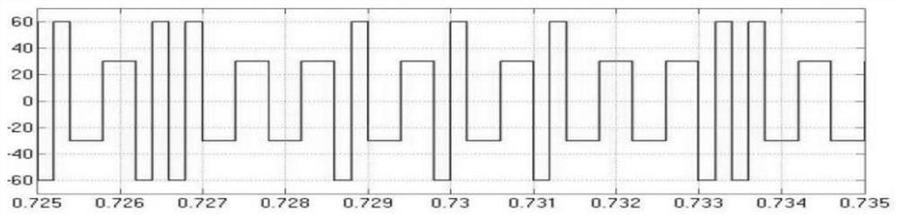
[0170] In the present invention, the random square wave signal injection used has a more significant effect on reducing the noise of the permanent magnet synchronous motor than the fixed frequency frequency signal injection, as follows:

[0171] 1) Spectrum diagram of motor current injected by fixed frequency square wave signal

[0172] inject as Figure 12 The fixed frequency square wave signal shown is a square wave signal with a square wave amplitude of 60V, a frequency of 2.5kHz, and a period T of 0.004s.

[0173] According to formula (15), the discrete spectral density can be obtained,

[0174]

[0175] Calculated by the above formula, the motor current spectrum diagram is as follows: Figure 14 As shown in (a), there are relatively obvious peaks in the motor current spectrum diagram, and their amplitudes are: 7.2dB, -0.1dB, -6.2dB; the peaks of the motor current spectrum diagram represent noise. The larger the amplitude of the spike, the correspondingly larger the ...

Embodiment 2

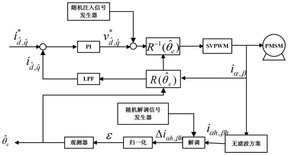
[0184] In another preferred embodiment of the present invention, due to the nonlinearity of the inverter, the actual high-frequency voltage signal is distorted. Taking the d-axis as an example, the d-axis appears as δu dh voltage error, so that the injected voltage is stepped, resulting in an induced current produce non-linear effects such as Figure 15 (a) shown.

[0185] Therefore, based on Figure 6 The principle of the high-frequency injection method for real-time adjustment of the amplitude shown in the figure, K in the figure ph is the proportional coefficient of the PI regulator; K ih is the integral coefficient; Tsamp is the sampling time; z is the discretization operator; the error is eliminated by constructing a regulator, as shown in the following formula (29):

[0186]

[0187] In the formula, Indicates the error between the actual angle and the estimated angle; Δi qh Indicates the q-axis current change value; Δi dh Indicates the d-axis current change...


PUM


Abstract

The invention discloses a position sensorless control method of a high-speed permanent magnet synchronous motor. The control method can improve the dynamic performance of the high-speed permanent magnet synchronous motor at rest or running in a low-speed area while reducing the noise generated by the traditional high-frequency injection method, and It can ensure the stable operation of the motor during dynamic operations such as sudden loading and unloading.

Description

technical field [0001] The invention belongs to the field of motor control, and in particular relates to a position sensorless control method for a high-speed permanent magnet synchronous motor. Background technique [0002] As the power source of high-speed transmission technology, high-speed AC motors are widely used in aerospace, flywheel energy storage, high-precision CNC machine tools, and distributed energy. Permanent magnet synchronous motors have the advantages of high efficiency and high power density, and are widely used in high-speed systems. However, since the rated frequency of the high-speed motor is generally above 500Hz, and the inverter is limited by the heat dissipation capacity of the device, the switching frequency cannot be too high. The high-speed motor control method needs to satisfy the operating condition that the ratio between the switching frequency of the inverter and the fundamental wave operating frequency of the motor is low, that is, the low ...

Claims


Application Information

Patent Timeline
Patent Type & Authority Patents(China)
IPC IPC(8): H02P6/18H02P21/18
CPCH02P6/183H02P21/18H02P2203/11Y02E60/16
Inventor 苑国锋张宝利
Owner NORTH CHINA UNIVERSITY OF TECHNOLOGY
Why Eureka
Try Eureka