

High-voltage shock wave generation system for cardiovascular stenosis lesions
A technology for generating systems and shock waves, used in medical science, surgery, etc., can solve the problems of inability to detect and control pulse release energy, inability to achieve continuous adjustment of pulse voltage, and high requirements for component withstand voltage, and achieve long-term maintenance of blood vessels. Generally, the effect of reducing heat release and equipment cost is low
- Summary
- Abstract
- Description
- Claims
- Application Information
AI Technical Summary
Problems solved by technology
Method used
Image

Examples
Embodiment 1
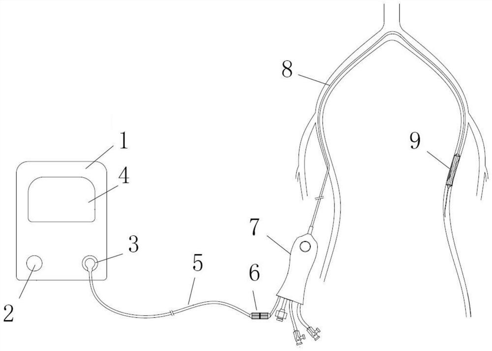
[0052] A high-voltage shock wave generating system for cardiovascular stenosis, the system includes an energy generator 1, the energy generator 1 includes an energy storage device and an energy release control device, and the energy release control device includes a high-voltage pulse circuit, An electrode selection circuit and a release state detection circuit; the high-voltage pulse circuit is a topological structure, and the high-voltage pulse circuit includes positive poles, negative poles, capacitors, diodes and switches.
[0053] Further, the high-voltage pulse circuit includes n loops, where n is 2-100, and the loops include capacitors, diodes and switches.
[0054] Further, the capacitor includes a single-stage capacitor or a multi-stage capacitor, and the multi-stage capacitor includes one or a combination of multiple capacitors connected in series, multiple capacitors connected in parallel, multiple capacitors connected in series first and then connected in parallel a...
Embodiment 2
[0066] This embodiment is carried out on the basis of the above-mentioned embodiment 1, and the similarities with the above-mentioned embodiment will not be repeated.
[0067] This embodiment mainly introduces a circuit topology to realize high-voltage pulses.
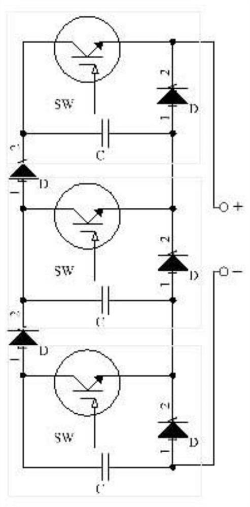
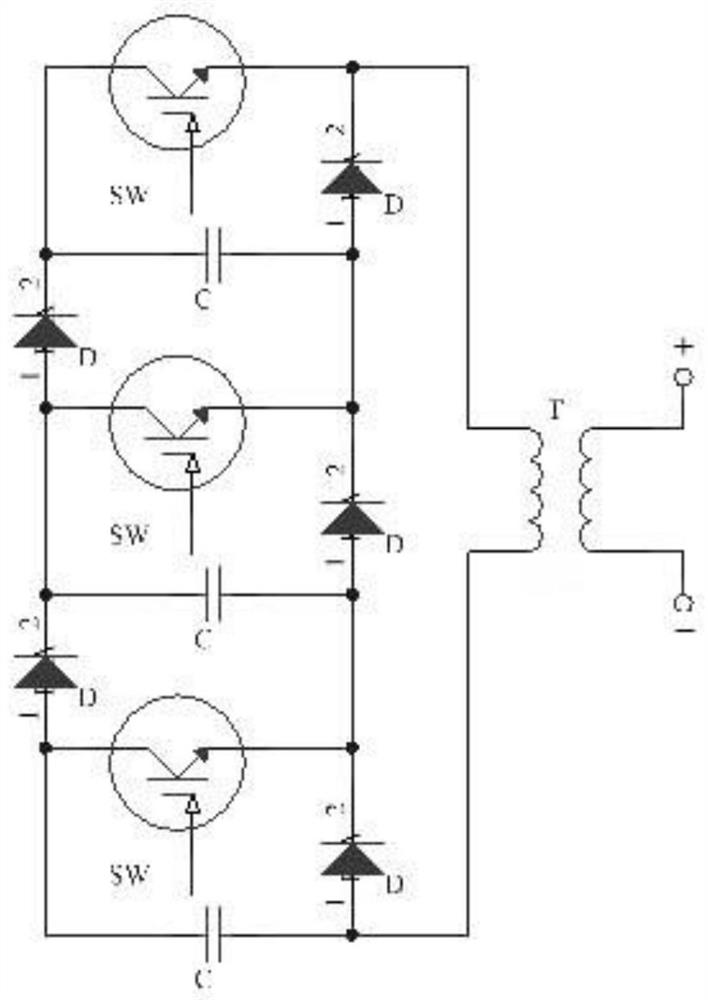
[0068] The pulse circuit includes a positive pole, a negative pole and n loops, n is a natural number greater than 1, each loop includes a capacitor C, a diode D, and a switch SW, and each loop is provided with three nodes.
[0069] Further, the release voltage range of the pulse circuit is 300V-20000V.
[0070] Further, by boosting the voltage through capacitor energy storage, and then discharging in series, the divided voltage on the m switches is one m of the total voltage, and m is a natural number greater than 1, which can reduce the withstand voltage requirements of each switch, so that Use a switch with low withstand voltage and fast switching speed to realize fast switching, the switching speed can be controll...
Embodiment 3
[0075] This embodiment is carried out on the basis of the above-mentioned embodiment 2, and the similarities with the above-mentioned embodiment will not be repeated.
[0076] as attached figure 2 As shown, the pulse circuit includes 5 loops, and each loop includes a capacitor C, a diode D, and a switch SW.
[0077] Further, the switch is a single-stage switch.
[0078] Further, the capacitor is a single-stage capacitor.
[0079] Further, the voltage is boosted through capacitor energy storage, and then discharged in series, and the divided voltage on the three switches is one-third of the total voltage.
[0080] Further, by connecting five groups of currents in parallel, the current divided by each switch is one-fifth of the total current.
PUM
| Property | Measurement | Unit |
|---|---|---|
| Pulse width | aaaaa | aaaaa |
Abstract
Description
Claims
Application Information