Supercharge Your Innovation With Domain-Expert AI Agents!

Large-octave ultra-wide angle scanning phased array antenna

A phased array antenna and wide-angle scanning technology, which is applied to the antenna, antenna grounding switch structure connection, electrical components, etc., can solve the problems of limited high power resistance performance, unpromoted, limited scanning angle, etc.

Active Publication Date: 2021-04-23
扬州船用电子仪器研究所
View PDF4 Cites 0 Cited by
  • Summary
  • Abstract
  • Description
  • Claims
  • Application Information

AI Technical Summary

Problems solved by technology

[0003] In 2011, M.Wajih Elsallal of Rockwell Collins Company of the United States published the article "AnUltra-Thin, Decade(10:1) Bandwidth, Modular "BAVA" Array with Low Cross-Polarization" at an international conference, proposing the 10-octave ( 1.8-18GHz) U-shaped coupling capacitor slot-loaded balanced anti-heel Vivaldi ultra-wideband antenna array, which can realize ±45° scanning of E-plane and H-plane, but when the array H-plane scans to 45°, the active standing wave is at 1.8 The -11.5GHz frequency band is greater than 4. Due to the high processing and assembly precision of the U-shaped coupling capacitor slot, it is very difficult to realize the project, and it has not been promoted at present.
In 2016, the John L. Volakis team of Ohio State University published the article "Dual-Polarized Tightly Coupled Array With Substrate Loading" in IEEE Antennas and Wireless Propagation Letters, and designed a 13.1-octave dipole array antenna based on tight coupling theory. , the maximum scanning angle of the E and H planes of the antenna array is 45°, and the efficiency is only 60% due to the use of lumped resistors to absorb echoes
Absorptive elements make thermal management of the panel difficult at high power operation
In 2019, the John L. Volakis team published "Dual-linear Polarized Phased Array with 9:1 Bandwidth and 60°Scanningoff Broadside" in IEEE Transcation on Antenna and Propagation, and designed a 9-octave (2-18GHz) large-angle scanning The tight-coupled dipole array antenna, the maximum scanning angle of the E-plane and H-plane of the antenna array is 60°, but the active standing wave of the low-frequency end H-plane is as high as 6 when scanning at 60°, and the efficiency is only 50%. The thickness of the antenna dielectric plate is only 0.254mm, it is difficult to adapt to the harsh working environment, and the performance of high power resistance is limited
Lower aperture efficiency means that the number of antennas needs to be increased to meet the required performance, which will greatly increase the cost of the system
In addition, the assembly of the above-mentioned antenna array is difficult, and the reliability needs to be verified by engineering
[0005]As mentioned above, in the existing literature reports, the large-octave ultra-wideband phased array antenna has a limited scanning angle (≤45°) and a large scanning angle. Active standing waves are too large (>4), low efficiency (<60%), etc. In order to ensure efficient operation in the entire frequency band, it is necessary to increase the number of channels of the phased array system, which greatly increases the cost

Method used


Image

  • Large-octave ultra-wide angle scanning phased array antenna
  • Large-octave ultra-wide angle scanning phased array antenna
  • Large-octave ultra-wide angle scanning phased array antenna

Examples


Embodiment

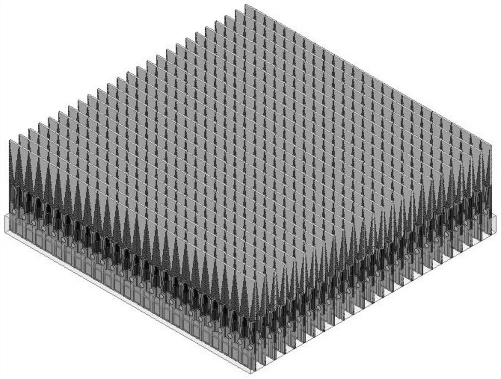
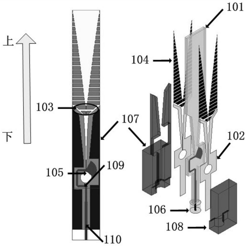
[0033] A large-octave ultra-wide-angle scanning phased array antenna in this embodiment adopts a 21×21 planar array form, as shown in Figure 1. Its basic antenna unit structure is as follows figure 2As shown, the antenna unit is a dielectric-metal structure composed of a double-sided printed microwave dielectric board 101 and a metal structure 107 . The microwave dielectric plate 101 has a thickness of 1mm and a dielectric constant of 2.2, and has been tapered in shape, and the tapered surface is wrapped by the metal of the structural member 107, so as to suppress the high-order mode propagating laterally along the interior of the substrate. The spacing between the antenna elements is half a wavelength of high frequency to prevent grating lobes in the scanning space, and the height of the antenna elements is 3.5 times the high frequency wavelength to ensure good radiation performance in the whole frequency band.

[0034] The same pattern is printed on the uppermost layer and...


PUM


Abstract

The invention discloses a large-octave ultra-wide angle scanning phased array antenna. The antenna comprises two layers of tapered microwave dielectric substrates, short Vivaldi antennas, two sections of gradient strip lines, exponential gradient radiation current sheets, coupling patches, metal fixing pieces, microwave coaxial cables and and dielectric substrate metal covered edges; the short Vivaldi antennas are printed on the upper surface and the lower surface of each microwave dielectric substrate and serve as antenna main radiation structures; the two sections of gradient strip lines are positioned between the two layers of microwave dielectric substrates and are used for impedance conversion; the exponential gradient radiation current sheets are printed on the upper surfaces and the lower surfaces of the microwave dielectric substrates, are positioned at the front ends of the short Vivaldi antennas and are used as secondary radiation structures; the coupling patches are used for energy transmission between the short Vivaldi antennas and the gradient radiation current sheets; the metal fixing pieces can be shaped to be matched and connected with the dielectric substrates; the microwave coaxial cables are positioned at the tail ends of the dielectric substrates and are used for feeding the gradient strip lines; and the dielectric substrate metal covered edges are used for suppressing a high-order mode. The antenna has the radiation characteristic of high aperture utilization rate in a large octave and ultra-wide angle scanning range.

Description

technical field [0001] The invention belongs to the technical field of microwave antennas, in particular to a large-octave ultra-wide-angle scanning phased array antenna. Background technique [0002] The electronic system of the future battlefield will have the typical characteristics of multi-function, integrating multiple functions into one body to reduce the mutual interference of each subsystem, thereby improving the resource scheduling capability and combat effectiveness of the equipment system. As the transceiver front-end of the above-mentioned electronic system, the antenna array is often required to have working capabilities such as large-octave ultra-wideband, ultra-wide-angle scanning, and high aperture utilization. Tightly coupled dipole antennas, log-periodic antennas, Vivaldi antennas, etc. are often used in existing broadband phased array antenna systems. [0003] In 2011, M.Wajih Elsallal of Rockwell Collins Company of the United States published the articl...

Claims


Application Information

Patent Timeline
IPC IPC(8): H01Q1/36H01Q1/50H01Q3/34
CPCH01Q1/36H01Q1/50H01Q3/34
Inventor 李祥祥陶静项永华李业强陈玉山
Owner 扬州船用电子仪器研究所
Features
  • R&D
  • Intellectual Property
  • Life Sciences
  • Materials
  • Tech Scout
  • Unparalleled Data Quality
  • Higher Quality Content
  • 60% Fewer Hallucinations
Learn More