High-frequency modulation motor position detection device
A technology of motor position and detection device, applied in circuit devices, control systems, electrical components, etc., can solve the problems of non-constant equivalent impedance of sensing elements, incomplete solutions, and inability to fully utilize the detection principle.
- Summary
- Abstract
- Description
- Claims
- Application Information
AI Technical Summary
Problems solved by technology
Method used
Image
Examples
Embodiment 1
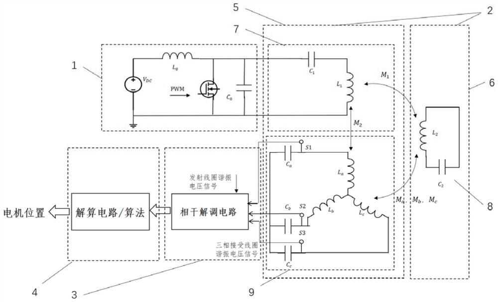
[0051] refer to figure 2 As shown, this embodiment relates to a high-frequency modulation motor position detection device, which includes a high-frequency excitation circuit 1, a sensing element 2 and a demodulation and calculation circuit, wherein the high-frequency excitation circuit 1 has at least one high-frequency switching device, Realize the specific carrier frequency narrow-band alternating voltage excitation of the sensing element; the sensing element at least includes a transmitting coil 7 and a receiving coil 9 consolidated with the motor stator 5 and a feedback coil 8 consolidated with the motor rotor 6, the The transmitting coil 7 is connected to the high-frequency excitation circuit 1. Under the excitation of the specific carrier frequency narrow-band alternating voltage, the transmitting coil 7, the feedback coil 8 and the receiving coil 9 work in a resonant state, and the connection between the feedback coil and the receiving coil The mutual inductance between...
Embodiment 2
[0065] For the demodulation circuit of the received signal of the sensor, another alternative is to use an operational amplifier to convert the bilateral modulation signal into a single-sided modulation, and use the envelope detection, gain adjustment circuit and filter circuit to obtain the envelope. The peak detection process is as follows: Figure 11 As shown, the schematic diagram of the circuit is shown in Figure 12 shown. The addition circuit is constructed by using the operational amplifier to superimpose the received signal and the carrier signal. Let one of the phase receiving signals be U x =Acosθsin(2πft), the carrier signal is U y =Bsin(2πft), by Figure 12 The matching of resistors R1, R2 and R3 in, the output signal is:
[0066]
[0067] Therefore, a unilaterally modulated output signal can be obtained.
[0068] Using a diode peak detector circuit, the envelope of the modulated signal is extracted. Since the envelope already has a positive bias, it is o...
PUM
 Abstract
Description
Claims
Application Information
 - R&D
- Intellectual Property
- Life Sciences
- Materials
- Tech Scout
- Unparalleled Data Quality
- Higher Quality Content
- 60% Fewer Hallucinations
Browse by: Latest US Patents, China's latest patents, Technical Efficacy Thesaurus, Application Domain, Technology Topic, Popular Technical Reports.
© 2025 PatSnap. All rights reserved.Legal|Privacy policy|Modern Slavery Act Transparency Statement|Sitemap|About US| Contact US: help@patsnap.com


