Integrated power battery thermal management system with cooling and fire extinguishing functions

A thermal management system and power battery technology, applied in secondary batteries, refrigeration and liquefaction, lighting and heating equipment, etc., can solve the problems of heavy mass, small latent heat of phase change, and difficult preheating of thermal management methods of phase change materials.

Inactive Publication Date: 2021-04-30
HARBIN ENG UNIV
View PDF8 Cites 6 Cited by
  • Summary
  • Abstract
  • Description
  • Claims
  • Application Information

AI Technical Summary

Problems solved by technology

The heat management method of air-cooled power batteries is due to the small specific heat capacity of air, low thermal conductivity, small convective heat transfer coefficient, long time required for heat dissipation, poor cooling effect at high charge and discharge rates, and large inlet and outlet pressure differences of the entire system. Uneven, the difference in cooling conditions between the cells in the battery pack will lead to a large temperature difference in the battery pack, which has been gradually eliminated by the main engine factory
The thermal conductivity of phase change materials is low, the latent heat of phase change is small, and the amount of heat transfer is limited. It requires additional system volume and heavy weight, which greatly reduces the mass energy density and volume energy density of the entire thermal management system, and cannot dissipate heat in time. The problem of difficult preheating in thermal management of phase change materials is even more difficult to solve
Heat pipes and batteries have high requirements for shape adaptability, complex structures, poor heat transfer performance, high insulation requirements, high processing technology requirements and high costs

Method used


Image

  • Integrated power battery thermal management system with cooling and fire extinguishing functions
  • Integrated power battery thermal management system with cooling and fire extinguishing functions

Examples


Embodiment Construction

[0018] The present invention is described in more detail below in conjunction with accompanying drawing example:

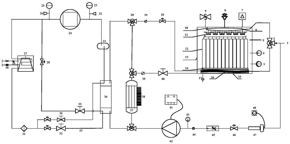
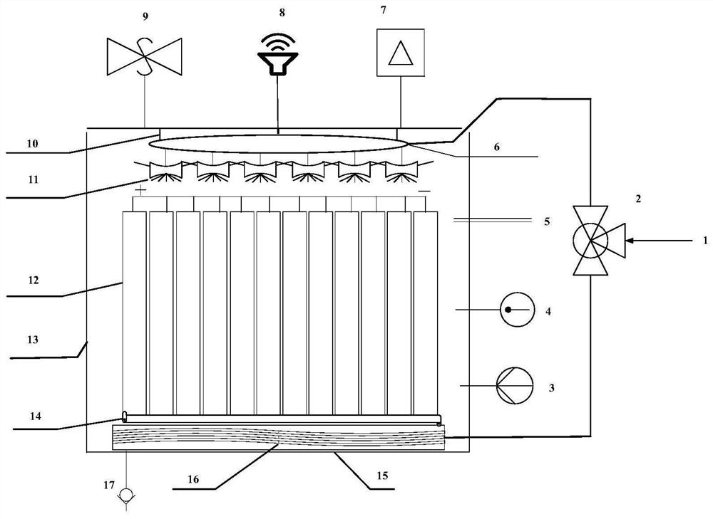
[0019] combine Figure 1-2 , the present invention provides an integrated power battery thermal management system with cooling and fire extinguishing functions, by setting a temperature / pressure / gas multifunctional sensor in a closed battery liquid tank, the state data monitored by the sensor is transmitted to the signal controller , The signal controller controls the entire thermal management system to operate the liquid cooling unit or liquid fire extinguishing unit. The atomizing nozzles on the liquid fire extinguishing unit adopt a disc-shaped arrangement, which can improve the spray coverage. The invention integrates the functions of heat dissipation, preheating and fire extinguishing, has good heat exchange effect, wide application range and high practical value.

[0020] Such as figure 1 As shown, an integrated power battery thermal management system with...


PUM


Abstract

The invention aims to provide an integrated power battery thermal management system with cooling and fire extinguishing functions. A compressor, a condenser, a dry filter, a refrigeration electromagnetic valve, a capillary tube and an evaporator are sequentially connected to form a compressor unit refrigeration unit; a manual valve and a liquid spraying electromagnetic valve are led out from the front of the refrigerating electromagnetic valve to form a spraying branch; a manual valve and a thermal electromagnetic valve are led out from a pipeline between the compressor and the condenser to form a thermal bypass branch; a first three-way connecting valve, a water absorption filter and a regulating valve are connected to a liquid outlet of a liquid cooling plate in the battery liquid tank to form a liquid cooling branch, and the second three-way connecting valve, the water absorption filter and the liquid return electromagnetic valve are connected to a liquid return port of the sealed battery liquid tank to form a liquid fire extinguishing branch; the circulating pump, the temperature sensor, the flow sensor, the flow regulating valve, the diaphragm valve and the heater are sequentially connected to form a liquid cooling circulating unit. Cooling and fire extinguishing functions are integrated, the space utilization rate of the system can be increased, and the safety performance of the whole thermal management system is enhanced.

Description

technical field [0001] The invention relates to a power battery management system. Background technique [0002] Power battery, motor and electronic control technology are the core "three electric" components of new energy vehicles, and their performance has an important influence on the whole vehicle. In particular, the current power battery is developing in the direction of high energy density and short charging time. The high heat output of the power battery requires a thermal management system to dissipate heat quickly to ensure that the entire battery module or battery pack is in a suitable operating temperature range and the system is different. Location cell temperature uniformity. [0003] At present, the existing battery thermal management methods mainly include: air cooling, liquid cooling, phase change material cooling and heat pipe cooling. The heat management method of air-cooled power batteries is due to the small specific heat capacity of air, low thermal co...

Claims


Application Information

Patent Timeline
Patent Type & Authority Applications(China)
IPC IPC(8): B60L58/26B60L58/27B60L3/00F25B1/00A62C3/07A62C3/16A62C31/00A62C37/38H01M10/613H01M10/615H01M10/625H01M10/635H01M10/6567
CPCB60L58/26B60L58/27B60L3/0046F25B1/00A62C3/07A62C3/16A62C31/005A62C37/38H01M10/613H01M10/615H01M10/625H01M10/635H01M10/6567Y02T10/70Y02E60/10
Inventor 范立云李奎杰陈雅毛运涛钟鑫王鑫浩高新宇
Owner HARBIN ENG UNIV
Why Eureka
Try Eureka