Dual-optical frequency comb generation system and generation method

A dual-optical frequency comb, optical frequency comb technology, applied in the direction of lasers, laser parts, electrical components, etc., can solve the problems of increasing the interval between comb teeth, no obvious advantages, and high repetition frequency, and achieve high single comb tooth power, Convenient measurement and locking, spectral flattening effect

Active Publication Date: 2021-05-04
南京南辉智能光学感控研究院有限公司
View PDF6 Cites 1 Cited by
  • Summary
  • Abstract
  • Description
  • Claims
  • Application Information

AI Technical Summary

Problems solved by technology

Among them, the traditional mode-locked femtosecond laser to realize the dual optical frequency comb system is complex, bulky and costly
Although the use of electro-optic modulation or Kerr nonlinearity can realize dual optical frequency combs in microcavities, thereby realizing the miniaturization of dual optical frequency combs and even chip integration, but the repetition frequency of these microcavity optical frequency combs is high (GHz or even THz). , generally greatly exceeds the measurement range of traditional commercial electronic equipment, making the microcavity for low-cost locking of this type of dual optical frequency need to reach the order of millimeters
Moreover, its too high repetition frequency greatly increases the comb spacing, making it have no obvious advantages in some applications, such as ultra-long-distance ranging or fine spectroscopy

Method used


Image

  • Dual-optical frequency comb generation system and generation method
  • Dual-optical frequency comb generation system and generation method
  • Dual-optical frequency comb generation system and generation method

Examples


Embodiment 1

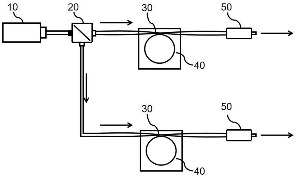
[0042] figure 1 A dual optical frequency comb generation system provided for this embodiment includes a pump laser 10 , a first optical splitter 20 , two coupling structures 30 , two optical microcavities 40 and an output port 50 . The pump laser 10 is used to provide pump light, and the pump light is split into two laser beams through the first beam splitter 20, such as figure 1 As shown, for clarity of description, the optical path at the top in the figure is recorded as the first optical path, and the optical path at the bottom is the second optical path; the first optical path is provided with a coupling structure 30, an optical microcavity 40 and an output port 50; Likewise, the second optical path is provided with a coupling structure 30 , an optical microcavity 40 and an output port 50 . The beam-splitting laser light is coupled into two coupling structures 30 respectively, and the two coupling structures 30 are used to respectively couple the beam-splitting pump laser...

Embodiment 2

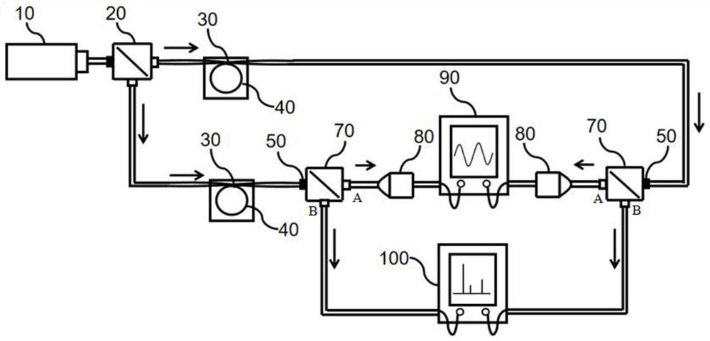
[0050] Such as figure 2 Shown is a schematic structural diagram of another dual optical frequency comb generating system provided in this embodiment. On the basis of embodiment 1 technical scheme, refer to figure 2 , the optical frequency comb generating system provided in this embodiment further includes two second beam splitters 70 , two photodetectors 80 , a spectrometer 90 and a spectrometer 100 .

[0051] The two output ends extending from the optical frequency comb output port 50 are respectively connected to the input ends of the second optical splitter 70, and the second optical splitter 70 is provided with at least two output ends (such as figure 2 The first output port A and the second output port B shown), the first output ports A of the two second optical splitters 70 are all connected to the input ports of the photodetector 80, and the output ports of the photodetector 80 are connected to the spectrum The instrument 90 is connected; the second output terminal...

Embodiment 3

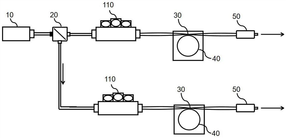
[0054] image 3 Shown is a schematic structural diagram of another optical frequency comb generation system provided in this embodiment. On the basis of embodiment 1 technical scheme, refer to image 3 , the optical frequency comb generation system provided in this embodiment also includes two polarization controllers 110, the first optical path and the second optical path are respectively provided with a polarization controller 110, and the polarization controllers 110 are respectively located in the beam splitter 20 and the two Between the coupling structures 30, a polarization controller 110 is used to adjust the polarization direction of the pump light.

[0055] Exemplarily, during specific implementation, by adjusting the two polarization controllers 110 to be in different states, the polarization direction of the pump laser light can be adjusted separately, so as to adjust the coupling efficiency of the pump light and the two optical mechanical microcavities 40 respecti...


PUM


Abstract

The invention discloses a dual-optical frequency comb generation system and method, pumping laser is divided into two beams of laser, the two beams of laser are respectively coupled into coupling structures, and the two coupling structures are used for respectively coupling the pump laser after light splitting into two light force microcavities; pump laser is transmitted in the light force microcavities to excite a light force microcavity optical mode, a mechanical mode is excited through light pressure, and an optical sideband, namely an optical frequency comb, is generated through the light force reaction. The comb tooth interval of the optical frequency comb is determined by the mechanical mode resonance frequency, so that the double optical frequency comb coherent with the original pump laser can be generated by selecting two optical coupling microcavities with slightly different mechanical mode resonance frequencies. The system and method can be used for producing a chip-integrated double-optical comb generation component with low cost.

Description

technical field [0001] The invention relates to micro-nano optical devices, in particular to an optical frequency comb generation system and generation method. Background technique [0002] Dual optical frequency comb technology has irreplaceable important applications in the fields of laser ranging and spectroscopy. The advantage is that it can greatly reduce the fuzzy distance of laser ranging, improve the information extraction rate, and reduce the difficulty of information demodulation. [0003] Typically, dual optical frequency combs can be obtained using two sets of optical frequency combs generated by mode-locked femtosecond lasers, electro-optic modulation, or Kerr nonlinearity. Among them, the traditional mode-locked femtosecond laser to realize the dual optical frequency comb system is complex, bulky and costly. Although the use of electro-optic modulation or Kerr nonlinearity can realize dual optical frequency combs in microcavities, thereby realizing the miniat...

Claims


Application Information

Patent Timeline
Patent Type & Authority Applications(China)
IPC IPC(8): H01S3/00
CPCH01S3/0085H01S3/0071
Inventor 丁舒林胡勇
Owner 南京南辉智能光学感控研究院有限公司
Why Eureka
Try Eureka