Glass kiln and glass product production device with same

A technology for glass furnaces and glass products, which is applied in glass furnace equipment, glass manufacturing equipment, manufacturing tools, etc., and can solve the problems of additional investment costs and operating costs

Active Publication Date: 2021-05-07
广州广钢气体能源股份有限公司
View PDF20 Cites 0 Cited by
  • Summary
  • Abstract
  • Description
  • Claims
  • Application Information

AI Technical Summary

Problems solved by technology

[0003] The purpose of the present invention is to overcome the deficiencies in the prior art, provide a glass kiln and a glass product production device with it, reduce the demand for oxygen p...

Method used


Image

  • Glass kiln and glass product production device with same
  • Glass kiln and glass product production device with same
  • Glass kiln and glass product production device with same

Examples


Embodiment 1

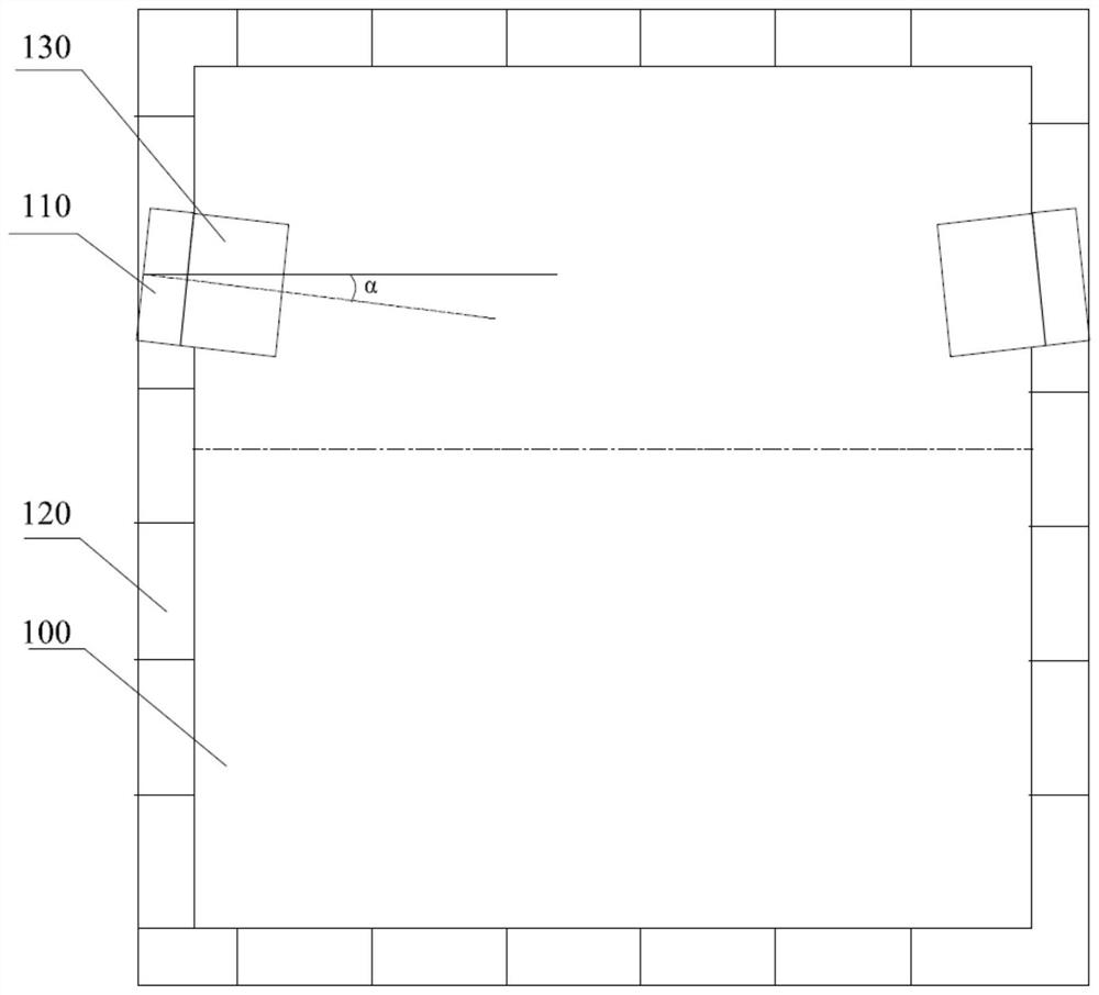
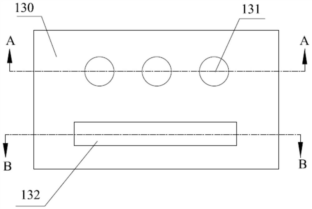
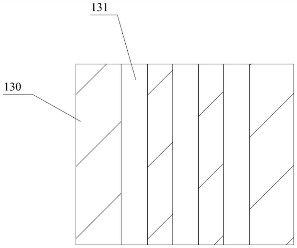
[0032] Such as Figure 1 to Figure 4 Shown is an embodiment of the glass furnace 100 of the present invention, which includes a furnace body 120 with at least two sets of parapet bricks 110. The parapet bricks 110 are equipped with nozzle bricks 130, and the nozzle bricks 130 are arranged inwardly toward the furnace body 120. The nozzle brick 130 is penetrated with a first nozzle 131 and a second nozzle 132, and the first nozzle 131 and the second nozzle 132 inject natural gas and oxygen into the furnace body 120 respectively, and the cross-sectional area of ​​the second nozzle 132 is larger than that of the first nozzle 132. A cross-sectional area of ​​the nozzle 131 . In this embodiment, the furnace body 120 is obtained by laying many bricks, the breast wall brick 110 is built and embedded in the brick body, and the nozzle brick 130 is installed on the breast wall brick 110 .

[0033] During the implementation of this embodiment, breast wall bricks 110 are arranged inwardly...

Embodiment 2

[0038] Such as Figure 5 Shown is an embodiment of the glass product production device of the present invention, including the glass furnace 100 as described in Embodiment 1, the forming assembly 200 for forming the glass liquid into a shape-fixed glass product 700, and the surface of the glass product 700 The polished polishing assembly 300 and the conveyor belt 400 for transporting the glass product 700, the glass furnace 100, the forming assembly 200 and the polishing assembly 300 are connected in sequence.

[0039] The glass raw material is melted in the glass furnace 100, and the molten glass enters the molding assembly 200 to cool down and finalize the shape. In industry, the molding assembly 200 is usually a mold composed of two halves, so that joint marks will be formed on the surface of the glass product 700. In addition, in the Factors such as uneven heating during the glass production process lead to different surface quality of the glass product 700 . During the p...


PUM


Abstract

The invention relates to the technical field of glass manufacturing, in particular to a glass kiln and a glass product production device with the glass kiln. A breast wall brick is provided with a nozzle brick, the nozzle brick inclines towards the interior of a kiln body, a first nozzle and a second nozzle penetrate through the nozzle brick, and the first nozzle and the second nozzle inject natural gas and oxygen into the kiln body respectively; the sectional area of the second nozzle is larger than that of the first nozzle. The requirement of the second nozzle for oxygen pressure is reduced, and an oxygen compressor does not need to be additionally arranged to meet the requirement for high oxygen pressure, so the field problem, the cost problem and the safety problem caused by additionally arranging the oxygen compressor are solved; in addition, in the production process of the glass product, the surface of the glass product is polished, so that joint marks and local bad surfaces can be eliminated, and the high-quality glass product is obtained.

Description

technical field [0001] The invention relates to the technical field of glass manufacturing, and more specifically, to a glass furnace and a glass product production device having the same. Background technique [0002] In recent years, due to the pressure of energy saving and environmental protection, more and more glass furnaces adopt pure oxygen combustion technology. The current pure oxygen combustion technology used in glass furnaces mostly adopts an integrated pure oxygen burner. Fuel and oxygen enter the pure oxygen burner separately, and are mixed and burned at the outlet to release heat. For example, Chinese patent CN106045279A discloses a nozzle brick for a glass kiln, which includes a brick body, and the brick body has a trumpet-shaped through hole; The inner diameter of the injection section decreases from outside to inside, and the injection section includes an outer injection section and an inner injection section; the inner diameters of the outer injection sec...

Claims


Application Information

Patent Timeline
IPC IPC(8): C03B5/00C03B29/00
CPCC03B5/00C03B29/00
Inventor 邓韬范胜标贲志山凌峰刘继雄高生明
Owner 广州广钢气体能源股份有限公司
Why Eureka
Try Eureka