Mass spectrum imaging high-spatial-resolution surface sampling head based on microfluidic technology and sampling method

A high spatial resolution, microfluidic technology, used in analytical materials, sample introduction/extraction, parts of particle separator tubes, etc. problems, to ensure applicability and safety, improve quality and effect, and achieve the effect of good biocompatibility

Active Publication Date: 2021-05-07
SHENZHEN INST OF ADVANCED TECH CHINESE ACAD OF SCI
View PDF4 Cites 0 Cited by
  • Summary
  • Abstract
  • Description
  • Claims
  • Application Information

AI Technical Summary

Problems solved by technology

[0004] 1) Large scale and low spatial resolution: the contact area between the mass spectrometer probe (sampling head) and the surface to be sampled is relatively large, the diameter of the sampling area is 2-5mm, and the sampling area is obviously larger than 10mm 2 , so the spatial resolution is low
Due to the limitations of the technology, the aforementioned invention has a resolution greater than 1mm and cannot be further improved.
[0005] 2) Long tube transmission loss and pollution: The mass spectrometer probe (sampling head) and the sample collected by the aforementioned patent need to be transmitted to the mass spectrometer through a long tube. Long-distance transmission of the sample will cause residual loss and pollution, which will affect the analysis effect
[0006] 3) The sampling process and the analysis process are highly coupled

Method used


Image

  • Mass spectrum imaging high-spatial-resolution surface sampling head based on microfluidic technology and sampling method
  • Mass spectrum imaging high-spatial-resolution surface sampling head based on microfluidic technology and sampling method
  • Mass spectrum imaging high-spatial-resolution surface sampling head based on microfluidic technology and sampling method

Examples


Embodiment

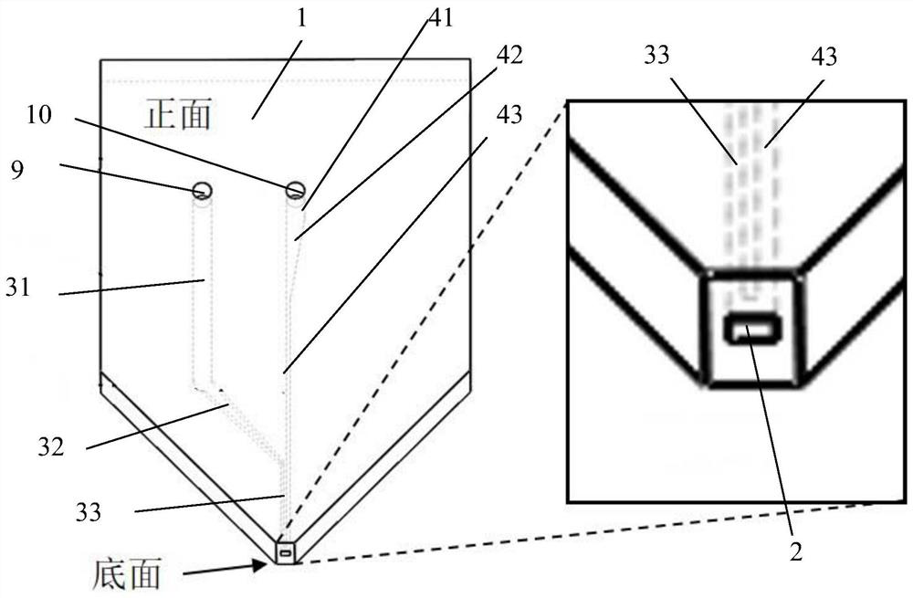
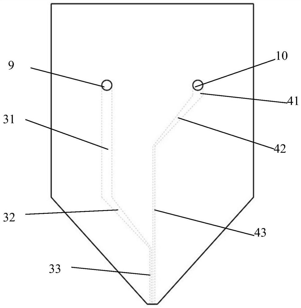
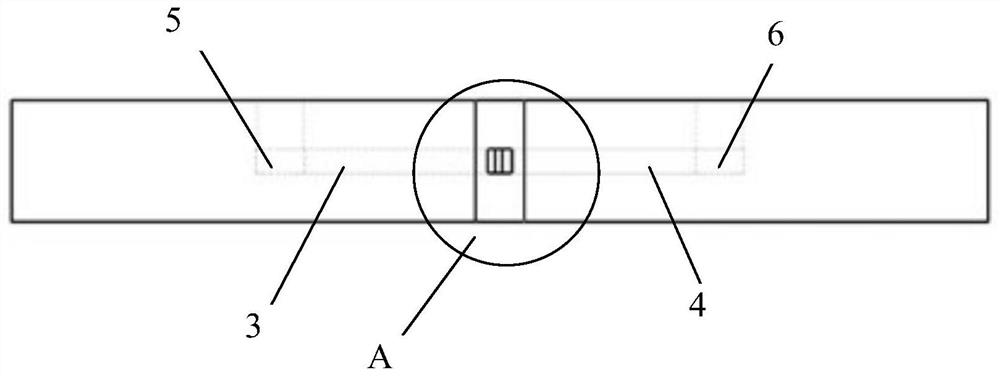
[0049] see Figure 1-Figure 5 , a high-spatial-resolution surface sampling head for mass spectrometry imaging based on microfluidic technology, is a semi-open cavity structure with double flow channel connections, as a whole.figure 1 shown. The sampling head body 1 has a sheet-like structure as a whole, with a small opening at the bottom, which is the sampling cavity 2; there are two round holes on the front of the sampling head body 1: the first round hole 9 and the second round hole 10, respectively connecting the two inner holes. Runners. The two flow channels inside the sampling head body 1 are the first flow channel 3 and the second flow channel 4 respectively, the first flow channel 3 is used for injecting the extraction solvent, and the second flow channel 4 is used for sample storage and ejection.

[0050] The sampling cavity 2 is a flat cuboid structure. When the bottom surface of the sampling head touches the surface of the object to be sampled horizontally, the sam...


PUM


Abstract

The invention relates to a mass spectrum imaging high-spatial-resolution surface sampling head based on a microfluidic technology and a sampling method. The mass spectrum imaging high-spatial-resolution surface sampling head based on the microfluidic technology comprises a sampling head body, the bottom of the sampling head body is provided with a sampling cavity, the sampling head body is internally provided with a first flow channel and a second flow channel, the first flow channel is used for injecting an extraction solvent, and the second flow channel is used for caching and spraying out a sample; each of the first flow channel and the second flow channel comprises a first interface and a second interface, the first interfaces of the first flow channel and the second flow channel are respectively communicated with the sampling cavity, and the second interfaces of the first flow channel and the second flow channel are respectively communicated with the outside of the sampling head body. The sampling cavity and the flow channels are designed, so that the sampling head has the characteristic of compact structure, meanwhile, the sampling spatial resolution and the sampling effect are improved, and the sampling head is provided with a planar design and a gas-liquid path interface, and can be conveniently combined with external movement equipment such as a robot and the like for use.

Description

technical field [0001] The invention relates to a mass spectrometry imaging high spatial resolution surface sampling head and a sampling method based on microfluidic technology. Background technique [0002] Mass spectrometry is an analytical method based on mass-to-charge ratio detection, and it is the only analytical method that can determine the structure of chemical molecules. [0003] The existing mass spectrometry technology uses a mass spectrometer pen to achieve sample extraction, however, the existing mass spectrometer pen has the following disadvantages: [0004] 1) Large scale and low spatial resolution: the contact area between the mass spectrometer probe (sampling head) and the surface to be sampled is relatively large, the diameter of the sampling area is 2-5mm, and the sampling area is obviously larger than 10mm 2 , so the spatial resolution is low. Due to the limitations of the process, the aforementioned invention has a resolution greater than 1 mm, which ...

Claims


Application Information

Patent Timeline
IPC IPC(8): H01J49/04G01N27/62G01N35/00
CPCH01J49/04G01N27/62G01N35/00
Inventor 罗茜邓卡潘挺睿吕悦广
Owner SHENZHEN INST OF ADVANCED TECH CHINESE ACAD OF SCI
Why Eureka
Try Eureka