
Industrial waste gas treatment and purification device

A purification device and industrial waste gas technology, applied in the direction of gas treatment, gaseous effluent wastewater treatment, combined devices, etc., can solve problems such as poor purification effect, increased labor costs, and difficulty in fully using equipment

Active Publication Date: 2021-05-18
苏州瑞优程芯科技有限公司
View PDF14 Cites 2 Cited by
  • Summary
  • Abstract
  • Description
  • Claims
  • Application Information

AI Technical Summary

Problems solved by technology

[0003] At present, some existing industrial waste gas treatment and purification devices are large in size and need to occupy a large area for construction, and it is inconvenient to disassemble and move for special use, and the construction cost is high. For some low-power equipment, the exhaust gas emission is not large, and the equipment is difficult It has been fully used, and the operation of the waste gas treatment equipment often requires professional personnel to operate and maintain it, which further increases the labor cost. At the same time, the connection between the waste gas treatment device and the waste gas discharge equipment is also difficult and cumbersome, which may easily lead to waste gas leakage, and the existing Some industrial waste gas treatment and purification devices have relatively simple purification methods, and the purification effect is not good

Method used


Image

  • Industrial waste gas treatment and purification device
  • Industrial waste gas treatment and purification device
  • Industrial waste gas treatment and purification device

Examples


Embodiment Construction

[0027] In order to make the object, technical solution and advantages of the present invention clearer, the present invention will be further described in detail below in combination with specific embodiments and with reference to the accompanying drawings. It should be understood that these descriptions are exemplary only, and are not intended to limit the scope of the present invention. Also, in the following description, descriptions of well-known structures and techniques are omitted to avoid unnecessarily obscuring the concept of the present invention.

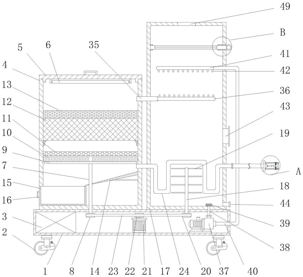
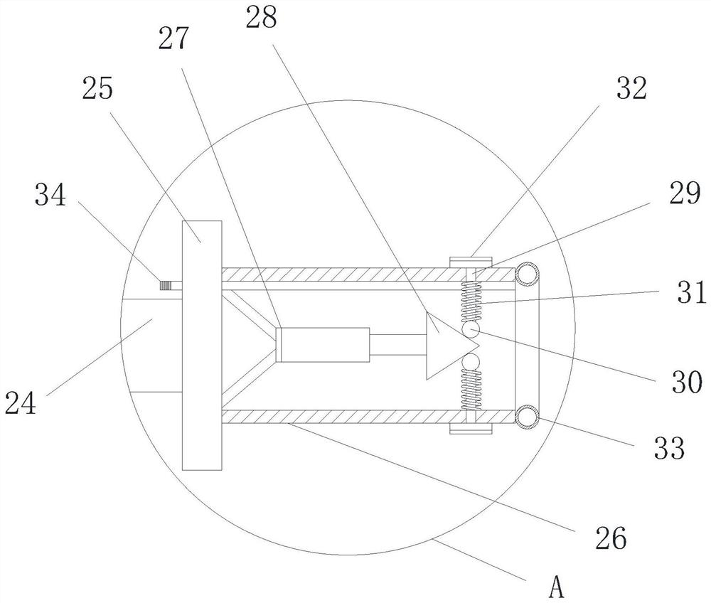
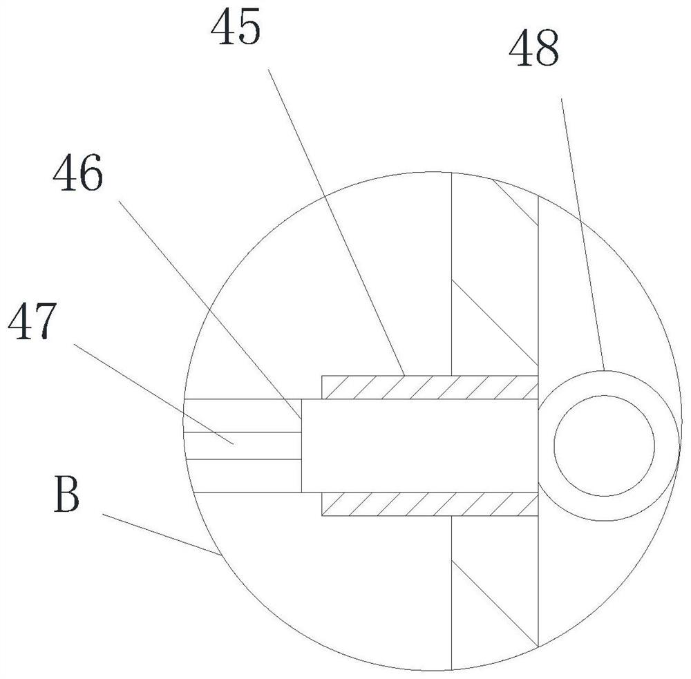
[0028] Such as Figure 1-4 As shown, an industrial waste gas treatment and purification device proposed by the present invention includes a base 1, a filter box 4 and a purification barrel 17, the base 1 is set as a hollow structure, and a number of moving wheels 2 are arranged on the left and right sides of the lower end of the base 1, A battery 3 is arranged on the left side inside the base 1, a filter box 4 is arrange...


PUM


Abstract

An industrial waste gas treatment and purification device comprises a base, a filter box and a purification barrel, wherein the base is of a hollow structure, the filter box is arranged on the left side of the upper end of the base, the upper end of the filter box is in threaded connection with an access cover, an ultraviolet lamp is arranged in the middle of the lower end of the access cover, a cleaning shaft is rotationally connected to the bottom end in the filter box, the lower end of the cleaning shaft penetrates through the filter box and the base and is connected with a first driven wheel, a cleaning cross rod is arranged at the upper end of the cleaning shaft, a brush is arranged at the upper end of the cleaning cross rod, and a filter screen plate is arranged on the lower side in the filter box. The device is rapid and convenient to mount and connect, stable and firm, excellent in sealing performance and good in cooling effect, the waste gas treatment efficiency and effect are improved through three filtration and adsorption layers in total, blockage can be avoided, sterilization and peculiar smell removal can be rapidly realized, dust, solid pollutants and the like in waste gas are further removed by means of cold water spraying, and the device is small in size, convenient to move and low in construction cost.

Description

technical field [0001] The invention relates to the technical field of waste gas treatment equipment, in particular to an industrial waste gas treatment and purification device. Background technique [0002] In recent years, with the development of the economy, various chemical, coating, furniture, toys, electronics, spraying and other enterprises have emerged in large numbers, coupled with insufficient investment in environmental protection, resulting in a large amount of industrial waste gas emissions, resulting in a decline in the quality of the atmospheric environment. It brings serious harm to human health, and different sizes of factories and equipment have different exhaust gas emissions. [0003] At present, some existing industrial waste gas treatment and purification devices are large in size and need to occupy a large area for construction, and it is inconvenient to disassemble and move for special use, and the construction cost is high. For some low-power equipme...

Claims


Application Information

Patent Timeline
IPC IPC(8): B08B15/02B08B15/04B01D46/00B01D47/06B01D50/00B01D53/74C02F1/52C02F103/18
CPCB08B15/02B08B15/04B01D47/06B01D53/007C02F1/5281C02F2103/18B01D2257/90B01D2257/91B01D2259/804B01D46/681B01D50/60
Inventor 黄柏良
Owner 苏州瑞优程芯科技有限公司
Learn More