Gas impurity removal and hydrolysis composite tank and blast furnace gas fine desulfurization system

A desulfurization system and coal gas refining technology, which is applied in the direction of gas dust removal, combustible gas purification, gas pollutant removal, etc., can solve the problems of high resistance and excessive pressure loss along the gas process

Pending Publication Date: 2021-05-18
上海轩鼎冶金科技集团有限公司
View PDF0 Cites 3 Cited by
  • Summary
  • Abstract
  • Description
  • Claims
  • Application Information

AI Technical Summary

Problems solved by technology

[0005] However, at present, the blast furnace gas enters the residual pressure turbine power generation device after the catalytic hydrolysis process. The greater the pressure of the gas entering the residual pressure turbine power generation device, the greater the power generation through the residua

Method used


Image

  • Gas impurity removal and hydrolysis composite tank and blast furnace gas fine desulfurization system
  • Gas impurity removal and hydrolysis composite tank and blast furnace gas fine desulfurization system
  • Gas impurity removal and hydrolysis composite tank and blast furnace gas fine desulfurization system

Examples


Embodiment 1

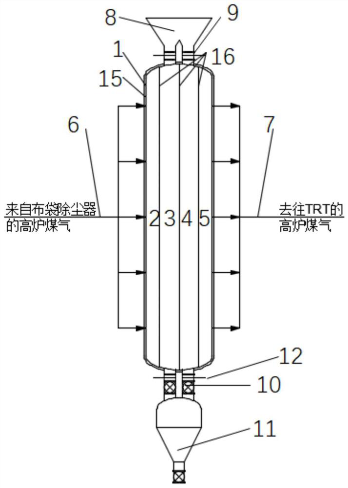
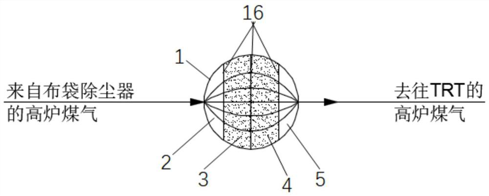
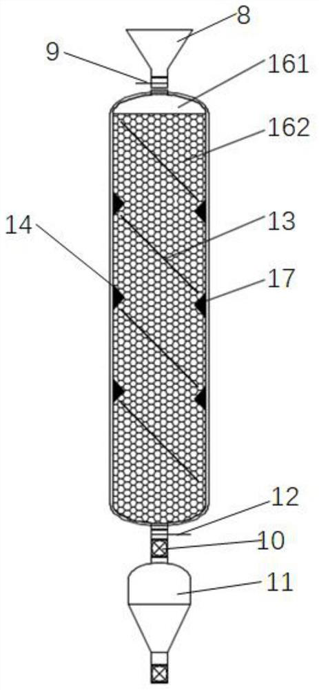
[0033] see figure 1 and figure 2 , a gas de-impurity hydrolysis composite tank, this embodiment is used for fine desulfurization of blast furnace flue gas, of course, it can also be used for other gases, including a reaction tank body 1, and the reaction tank body 1 is provided with a gas inlet 6 and a gas outlet 7 along the radial direction , three mesh partitions 16 are arranged inside the reaction tank body 1, and the mesh partitions 16 are arranged parallel to the center line of the reaction tank, and along the direction of radial gas flow, the mesh partitions 16 divide the interior of the reaction tank body 1 into a gas distribution chamber 2. The impurity removal chamber 3, the catalytic hydrolysis chamber 4 and the gas collection chamber 5, the gas inlet 6 is arranged on the peripheral side of the reaction tank body 1 close to the gas distribution chamber 2, and the gas outlet 7 is arranged on the reaction tank body 1 near the gas collection chamber 5 On the periphera...

Embodiment 2

[0047] like figure 1 , a blast furnace gas fine desulfurization system, including the gas removal and hydrolysis composite tank of the above-mentioned embodiment 1, a bag filter and a residual pressure turbine power generation device (TRT), the flue gas outlet of the bag filter is connected to the gas removal and hydrolysis composite tank The gas inlet 6 of the gas removal and hydrolysis composite tank is connected to the residual pressure turbine power generation device. The blast furnace flue gas is dedusted by the bag filter and then enters the impurity removal and hydrolysis composite tank to convert organic sulfides into easy-to-remove Hydrogen sulfide, and the pressure loss is small, and then the high-pressure blast furnace gas containing hydrogen sulfide generates electricity through the residual pressure turbine power generation device.


PUM


Abstract

The invention discloses a gas impurity removal and hydrolysis composite tank and a blast furnace gas fine desulfurization system. The gas impurity removal and hydrolysis composite tank comprises a reaction tank body, the reaction tank body is provided with a gas inlet and a gas outlet along the radial direction, three net partition plates are arranged in the reaction tank body, the net partition plates are parallel to the center line of the reaction tank, gas flows along the radial direction of the tank body, the interior of the reaction tank body is divided into a gas distribution chamber, an impurity removal chamber, a catalytic hydrolysis chamber and a gas collection chamber by the net partition plates, a gas inlet is formed in the gas distribution chamber side of the reaction tank body, a gas outlet is formed in the gas collection chamber side of the reaction tank body, an impurity removal agent is placed in the impurity removal chamber, an organic catalytic conversion agent is placed in the catalytic hydrolysis chamber, and gas enters the gas distribution chamber from the gas inlet, uniformly flows to the impurity removal chamber and the catalytic hydrolysis chamber, is converged in the gas collection chamber and then is discharged through the outlet, so that the on-way resistance of the gas is small, the pressure loss is small, and harmful impurities in the blast furnace flue gas can be removed, and organic sulfides can be catalytically hydrolyzed.

Description

technical field [0001] The invention belongs to the technical field of fine desulfurization of blast furnace gas, and in particular relates to a gas de-impurity hydrolysis composite tank and a blast furnace gas fine desulfurization system. Background technique [0002] At present, the blast furnace gas is only purified by the bag filter to remove the dust in the gas, so that the dust content of the gas is less than 10mg / m 3 Or lower, to meet the requirements of the subsequent process. However, the chemical composition of the gas has not changed. The chemical composition determines the composition of the flue gas after combustion. That is to say, the sulfur content of the blast furnace gas determines the SO content of the flue gas. 2 content. [0003] The output of blast furnace gas is large and there are many end users. If flue gas desulfurization (SO 2 ), there are many disadvantages such as many processing points, high investment, large land occupation and large labor q...

Claims


Application Information

Patent Timeline
IPC IPC(8): C10K1/00C10K1/02
CPCC10K1/004C10K1/024
Inventor 许建明
Owner 上海轩鼎冶金科技集团有限公司
Why Eureka
Try Eureka