Multi-dimensional integrated vehicle-mounted magnetic suspension flywheel battery control system

A flywheel battery and control system technology, applied in control systems, vector control systems, motor generator control, etc., can solve the problems of structural design dependence, complex control systems, and easy to fall into local extreme values.

Active Publication Date: 2021-05-18
JIANGSU UNIV
View PDF6 Cites 2 Cited by
  • Summary
  • Abstract
  • Description
  • Claims
  • Application Information

AI Technical Summary

Problems solved by technology

The parameter estimation method relies on the precise mathematical model of the system, which has high requirements for the design of the controller; the high-frequency signal injection method requires special signal processing technology to realize the displacement estimation; the sensorless control method based on the neural network uses the neural network The strong nonlinear mapping ability of the network realizes the self-detection of rotor displacement. Although this control method makes up for the shortcomings of the above two methods, the neural network currently has defects such as overfitting, easy to fall into local extremum, and structural design relying on experience.
The above three methods only consider low cost issues, and do not involve low energy consumption and stability issues
[0006] In addition, if the methods to solve the above problems are piled up in a control system in the form of decentralized modules, it will inevitably lead to a complex control system and affect the real-time response of the system. Still maintain high stability, low energy consumption and low cost running state control

Method used


Image

  • Multi-dimensional integrated vehicle-mounted magnetic suspension flywheel battery control system
  • Multi-dimensional integrated vehicle-mounted magnetic suspension flywheel battery control system
  • Multi-dimensional integrated vehicle-mounted magnetic suspension flywheel battery control system

Examples


Embodiment Construction

[0046] The present invention will be further described below in conjunction with the accompanying drawings and specific embodiments, but the protection scope of the present invention is not limited thereto.

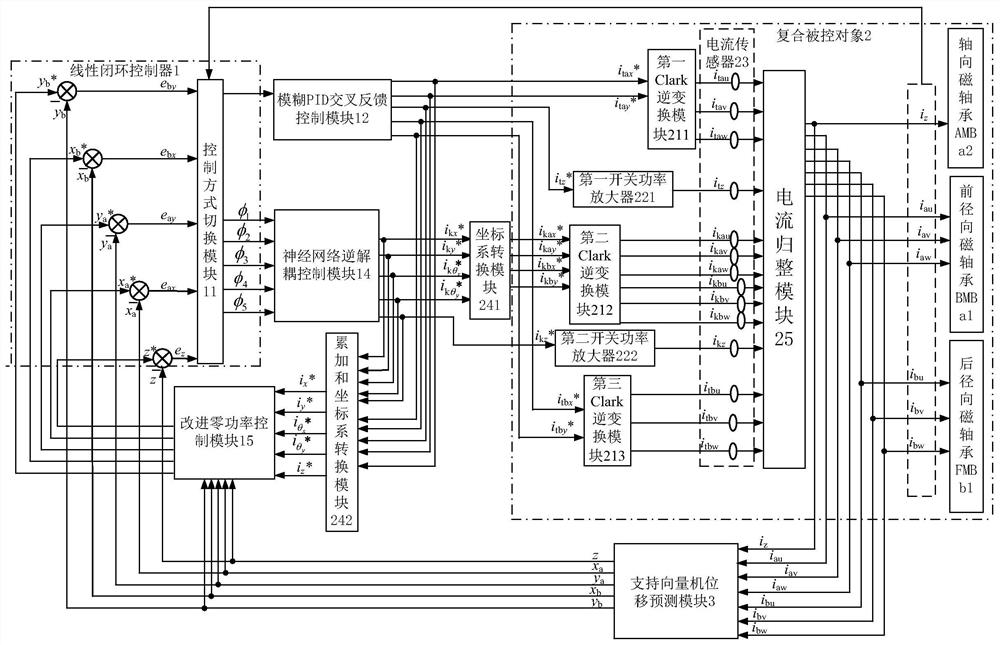
[0047] Such as figure 1 As shown, the multi-dimensional vehicle-mounted maglev flywheel battery control system includes a linear closed-loop controller 1, a fuzzy PID cross feedback control module 12, a neural network inverse decoupling control module 14, an improved zero-power control module 15, and a coordinate system conversion module 241. Accumulation and coordinate system conversion module 242 , compound controlled object 2 and support vector machine displacement prediction module 3 , and linear closed-loop controller 1 includes control mode switching module 11 .

[0048] Displacement deviation signal e in magnetic bearing coordinate system z 、e ax 、e ay 、e bx 、e by As an input, the second order derivative of the displacement signal φ is output by the control mo...


PUM


Abstract

The invention provides a multi-dimensional integrated vehicle-mounted magnetic suspension flywheel battery control system, and belongs to the technical field of vehicle-mounted flywheel battery control. According to the invention, a current signal processed by a current normalizing module is used as an input signal of a support vector machine displacement prediction module; an output signal of the support vector machine displacement prediction module and a signal which is output by the fuzzy PID cross feedback control module and the neural network inverse decoupling control module and is processed by the accumulation and coordinate system conversion module are used as input signals of the improved zero power control module; a displacement signal output by the support vector machine displacement prediction module and an output signal of the improved zero power control module are used as input signals of the linear closed-loop controller, and output of the linear closed-loop controller is used as input signals of the fuzzy PID cross feedback control module and the neural network inverse decoupling control module. According to the invention, the complexity of the whole system is simplified, the real-time response characteristic is greatly improved, the gyroscopic effect can be inhibited, the stability is improved, and the energy consumption and the cost are reduced.

Description

technical field [0001] The invention relates to the technical field of control of a vehicle-mounted magnetic levitation flywheel battery (also called a flywheel energy storage device) used for an electric vehicle, in particular to a vehicle-mounted magnetic levitation flywheel battery control system integrating low energy consumption, low cost, and high stability control. Background technique [0002] Vehicle-mounted magnetic levitation flywheel battery is a new mechatronic device based on magnetic levitation bearing technology. It breaks through the limitations of traditional chemical batteries and has the advantages of high energy storage density, high energy conversion rate, long service life, and no pollution. The stability control, energy consumption and cost of the flywheel rotor are the key factors affecting the popularization of the vehicle-mounted maglev flywheel battery. [0003] In terms of stability control: the driving state of the car itself and complex road co...

Claims


Application Information

Patent Timeline
Patent Type & Authority Applications(China)
IPC IPC(8): H02P21/00H02P21/18H02P21/22H02K7/02H02N15/00
CPCH02P21/001H02P21/0014H02P21/18H02P21/22H02K7/025H02N15/00Y02E60/16
Inventor 张维煜高映洁韩啸雅沈琳烽俞珏鑫
Owner JIANGSU UNIV
Why Eureka
Try Eureka