Carbonization furnace for secondary utilization of crude coal flue gas

A carbonization furnace and flue gas technology, which is used in stationary carbonization furnaces, coke ovens, petroleum industries, etc., can solve the problems of insufficient waste coal flue gas treatment capacity, shortened device service life, and high carbonization process costs, so as to avoid insufficient carbonization. , reduce the loss on ignition rate, avoid the effect of gray matter layer

Active Publication Date: 2021-05-28
阿拉善盟正杰环保科技研究有限公司
View PDF13 Cites 1 Cited by
  • Summary
  • Abstract
  • Description
  • Claims
  • Application Information

AI Technical Summary

Problems solved by technology

[0003] 1. Due to the ash layer formed on the surface of the carbonized material when the carbonized material contacts the surface of the carbonized material with an open flame, the activation time is long and the production cost is increased;
[0004] 2. Ordinary carbonization furnace equipment also needs external fuel supply, which consumes a lot of energy, and the waste coal smoke generated directly enters the incineration chamber for incineration and then is discharged into the atmosphere through the chimney tower, resulting in insufficient waste coal smoke treatment capacity and low output , resulting in high cost of the carbonization process and difficulty in meeting environmental protection standards;
[0006] 4. The tar produced during carbonization will be mixed in the raw coal flue gas. The tar impurities will cause corrosion and blockage of the devices in the carbonization furnace system (guide flue, axial fan, etc.), and it cannot be reasonably used The tar in the raw coal flue gas is separated, which shortens the service life of the device;

Method used


Image

  • Carbonization furnace for secondary utilization of crude coal flue gas
  • Carbonization furnace for secondary utilization of crude coal flue gas
  • Carbonization furnace for secondary utilization of crude coal flue gas

Examples


Embodiment Construction

[0031] The following will clearly and completely describe the technical solutions in the embodiments of the present invention with reference to the accompanying drawings in the embodiments of the present invention. Obviously, the described embodiments are only some, not all, embodiments of the present invention. Based on the embodiments of the present invention, all other embodiments obtained by persons of ordinary skill in the art without making creative efforts belong to the protection scope of the present invention.

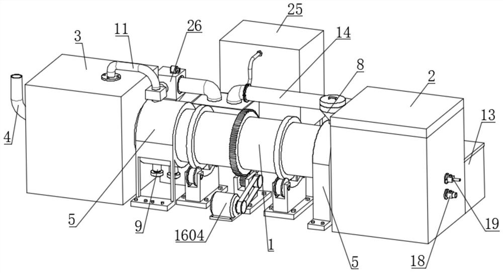
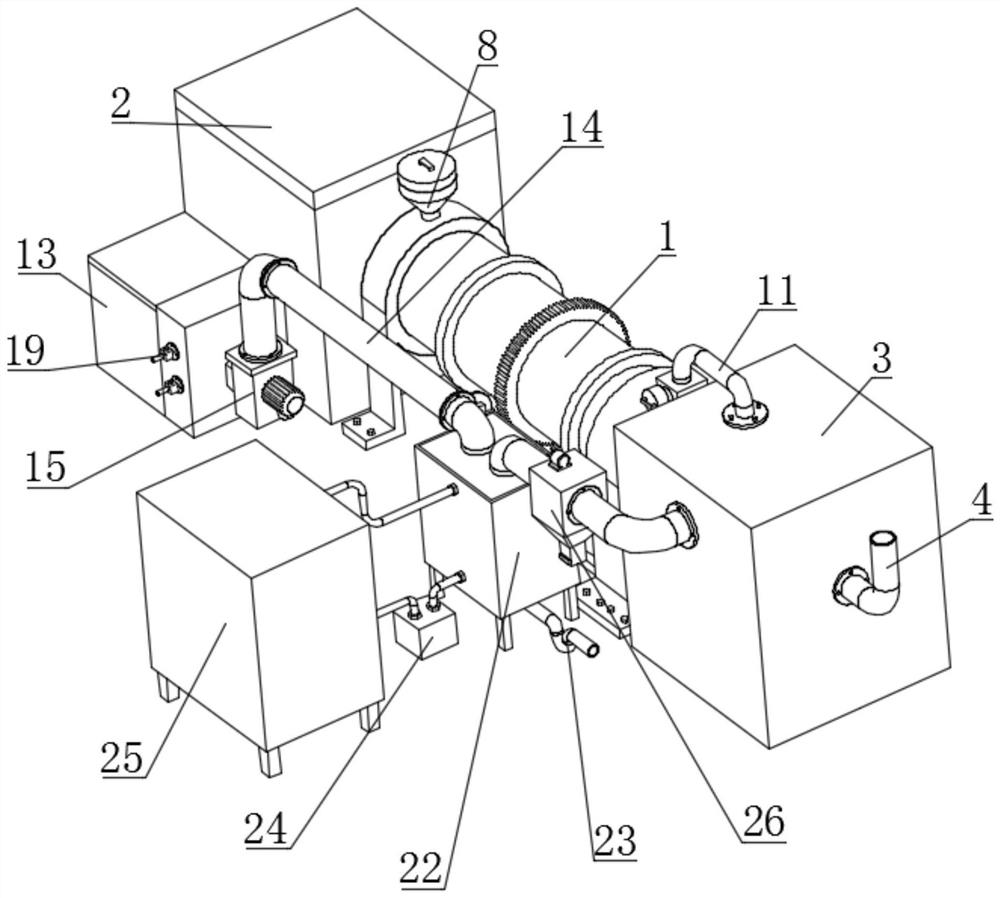
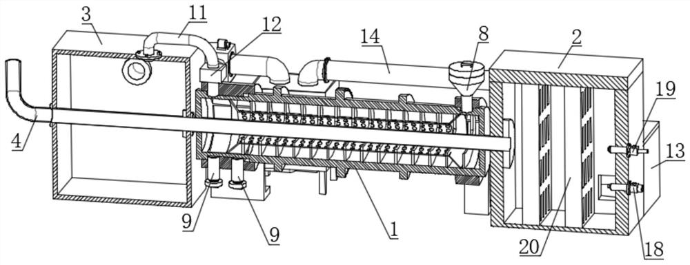
[0032] see Figure 1-11 , the present invention provides a technical solution: a carbonization furnace for secondary utilization of raw coal flue gas, including a tubular carbonization chamber 1 and a combustion furnace 2, and the two ends of the carbonization chamber 1 are respectively provided with a combustion furnace 2 and a flue gas The collection chamber 3 is used to provide heat when the interior of the combustion furnace 2 is in a combustion state. The...


PUM


Abstract

The invention discloses a carbonization furnace for secondary utilization of crude coal flue gas. The carbonization furnace comprises a tubular carbonization cavity and a combustion furnace, the combustion furnace and a flue gas collecting bin are arranged at the two ends of the carbonization cavity respectively, a lattice wall is arranged in the combustion furnace, the combustion furnace communicates with a heat radiation pipe, a screen drum for layering carbonized materials and a turbine for driving the carbonized materials to move are arranged in the carbonization cavity in the axis direction, the heat radiation pipe penetrates through the carbonization cavity and extends to the outside, and the screen drum and the turbine are driven by a driving mechanism to rotate along with the carbonization cavity. According to the invention, an axial flow fan is used for guiding the crude coal flue gas into a combustion chamber for sufficient combustion, so that the crude coal flue gas replaces natural gas or fire coal to reduce the production cost, and the carbonization cavity is in a sealed anaerobic state, so that the carbonized material cannot generate open fire in the carbonization cavity, spontaneous combustion of the carbonized material is avoided, the ignition loss rate of the carbonized material is effectively reduced, the carbonized material is prevented from generating an ash layer, and the product quality index and yield are improved.

Description

technical field [0001] The invention relates to the technical field of carbonization equipment, in particular to a carbonization furnace for secondary utilization of raw coal flue gas. Background technique [0002] At present, THL15160 internal heating carbonization furnace is mostly used in China. The carbonization process of this carbonization furnace is to add coal in the combustion chamber of the furnace head to generate heat radiation and spontaneous combustion of the formed strips for carbonization. The tower is discharged into the atmosphere, and its defects are as follows: [0003] 1. Due to the ash layer formed on the surface of the carbonized material when the carbonized material contacts the surface of the carbonized material with an open flame, the activation time is long and the production cost is increased; [0004] 2. Ordinary carbonization furnace equipment also needs external fuel supply, which consumes a lot of energy, and the waste coal smoke generated di...

Claims


Application Information

Patent Timeline
Patent Type & Authority Applications(China)
IPC IPC(8): C10B1/06C10B47/06
CPCC10B1/06C10B47/06
Inventor 邓金鹏
Owner 阿拉善盟正杰环保科技研究有限公司
Why Eureka
Try Eureka