
Energy storage device with heat recovery and conversion functions and energy storage method

A technology of conversion function and heat recovery, applied in circuit devices, separation methods, battery circuit devices, etc., can solve the problems of low conversion efficiency of equipment, environmental pollution, waste of thermal energy resources, etc.

Inactive Publication Date: 2021-05-28
南京罗朗智合电子科技有限公司
View PDF0 Cites 0 Cited by
  • Summary
  • Abstract
  • Description
  • Claims
  • Application Information

AI Technical Summary

Problems solved by technology

[0003] Common boilers need to use coal as fuel during operation. However, the flue gas produced by coal combustion is often allowed to be discharged into the atmosphere, causing inestimable pollution to the environment, and because the flue gas itself has A large amount of heat, direct discharge will lead to waste of heat energy resources, so it is necessary to design a boiler heat recovery device to solve this problem, although there have been some recovery equipment for boiler waste heat on the market, but the existing The equipment generally has the problem of low conversion efficiency

Method used


Image

  • Energy storage device with heat recovery and conversion functions and energy storage method
  • Energy storage device with heat recovery and conversion functions and energy storage method
  • Energy storage device with heat recovery and conversion functions and energy storage method

Examples


Embodiment Construction

[0029] The present invention will be further described below in conjunction with the examples.

[0030] The following examples are used to illustrate the present invention, but cannot be used to limit the protection scope of the present invention. The conditions in the embodiment can be further adjusted according to the specific conditions, and the simple improvement of the method of the present invention under the premise of the concept of the present invention belongs to the protection scope of the present invention.

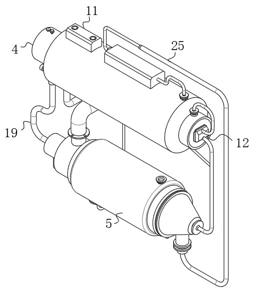
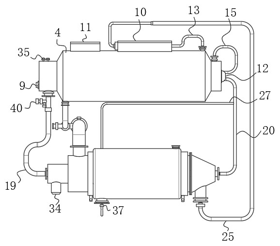
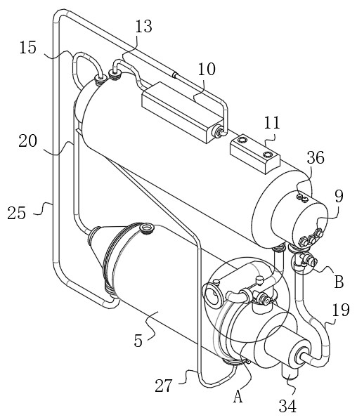
[0031] see Figure 1-8 , the present invention provides an energy storage device with heat recovery and conversion functions, including a waste heat inlet pipe 1, an energy storage module 2 and an energy conversion module 3, the energy storage module 2 includes an energy storage tank 4, and the energy conversion module Group 3 includes the transduction tank 5; the interior of the energy storage tank 4 is provided with an insulation layer 6, a secondary heat e...


PUM


Abstract

The invention discloses an energy storage device with heat recovery and conversion functions, and belongs to the technical field of energy recovery. The device comprises a waste heat inlet pipe, an energy storage module and an energy conversion module, the energy storage module comprises an energy storage tank, the energy conversion module comprises an energy conversion tank, a heat preservation layer, a secondary heat exchange cavity and a water storage cavity are sequentially arranged in the energy storage tank from outside to inside, and a set of electric heating rods are fixedly installed in the water storage cavity. An air filtering assembly, a storage battery and a pump body are fixedly installed on the peripheral side face of the energy storage tank, one end of a power supply port of the storage battery is electrically connected with the electric heating rods through wires, and a secondary hot air inlet pipe, a secondary hot air discharging pipe, a liquid inlet pipe and a liquid discharging pipe are fixedly installed on the peripheral side face of the energy storage tank respectively. Through the design of the energy storage module and the energy conversion module, the device can efficiently achieve the waste heat recovery and reutilization process of a boiler flue gas, and during work, the energy storage module and the energy conversion module can convert heat in waste heat into hot water energy and electric energy through a multi-stage heat exchange structure.

Description

technical field [0001] The invention belongs to the technical field of energy recovery, and in particular relates to an energy storage device with heat recovery and conversion functions. Background technique [0002] The hot water or steam generated in the boiler can directly provide the required heat energy for industrial production and people's life, and can also be converted into mechanical energy through a steam power device, or converted into electrical energy through a generator. [0003] Common boilers need to use coal as fuel during operation. However, the flue gas produced by coal combustion is often allowed to be discharged into the atmosphere, causing inestimable pollution to the environment, and because the flue gas produced after combustion has its own A large amount of heat, direct discharge will lead to waste of heat energy resources, so it is necessary to design a boiler heat recovery device to solve this problem, although there have been some recovery equipm...

Claims


Application Information

Patent Timeline
IPC IPC(8): F28D21/00F24H1/20F24H9/00F24H9/14F24H9/18F24H9/20H02J7/00H02N11/00B01D46/10B01D46/54
CPCB01D46/10B01D46/543B01D2258/06F24H1/201F24H9/0005F24H9/142F24H9/1818F24H9/2021F28D21/0003H02J7/00H02N11/002
Inventor 曾敬芬
Owner 南京罗朗智合电子科技有限公司
Learn More