Method for eliminating fuel cell coolant pollution

A fuel cell and fuel cell stack technology, applied in fuel cells, circuits, electrical components, etc., can solve problems such as proton exchange membrane pollution, affecting the performance output of fuel cell stacks, and poor stack voltage consistency. Pollution, recovery of MEA catalytic ability, and effect of stack performance improvement

Active Publication Date: 2021-05-28
SHANGHAI SHENLI TECH CO LTD
View PDF6 Cites 0 Cited by
  • Summary
  • Abstract
  • Description
  • Claims
  • Application Information

AI Technical Summary

Problems solved by technology

However, during improper operation or long-term use of the fuel cell stack, the fuel cell cooling system accessories (such as the intercooler) fail, causing the coolant in the coolant circuit to enter the fuel cell stack to generate carboxylate and other anions, which are harmful to the platinum of the MEA. The base catalyst or the proton exchange membrane will cause pollution, which will affect the performance output of the fuel cell stack
[0004] Chinese patent 201210090009.7 adopts air purging, then water flushing, and then air purging to eliminate anion, sulfate and ethylene glycol pollutants in the fuel cell, but the ethylene glycol entering the stack cannot be thoroughly cleaned by water flushing, and It can make the uncontaminated MEA also be polluted by ethylene glycol; there are few reports on the method of cleaning the coolant pollution in the fuel cell stack. In order not to affect the use of the stack, it is very effective to remove the coolant inside the stack. necessary
However, this treatment method has the following disadvantages: (1) The cleaning process involves a huge amount of work; (2) The cleaning process is likely to cause pollution or damage to the structural parts of the stack; Poor stack voltage consistency; (4) MEA and other materials and labor waste

Method used


Image

  • Method for eliminating fuel cell coolant pollution
  • Method for eliminating fuel cell coolant pollution
  • Method for eliminating fuel cell coolant pollution

Examples


Embodiment

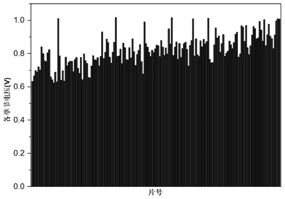
[0025] Such as figure 1 As shown, when the cooling system accessories (such as the intercooler) fail in the normal operation of the fuel cell stack, the antifreeze in the coolant circuit enters the interior of the fuel cell stack and the single-chip average value is detected by the fuel cell voltage inspection system. If the open circuit voltage is lower than 0.85V, it is judged that the fuel cell stack is polluted by coolant, and the following methods are used to eliminate the pollution of fuel cell coolant. The specific steps are as follows:

[0026] 1. Place the proton exchange membrane fuel cell polluted by the coolant on the test bench, and set the operating temperature of the fuel cell to 50-65°C. A certain flow rate of humidified oxidizing gas is used to purge the cathode and anode of the fuel cell at the same time. The above steps promote the desorption of anions such as carboxylate adsorbed on the surface of the MEA catalyst, and the direction of the purge gas intake ...

Embodiment 2

[0031] The oxidizing gas described in step (1) is pure oxygen or air, its working pressure is 1kPa, the flow rate is 1*nslpm, n is the number of fuel cell stacks, n≥1, the humidity is 30%, and the purge time is 60min.

[0032] The reducing gas described in step (2) is pure hydrogen, its working pressure is 1kPa, flow rate is 0.5*n slpm, n is the number of fuel cell stacks, n≥1, humidity is 30%, and purge time is 60min .

[0033] Step (3) When the fuel cell stack is activated, the air at the cathode and the hydrogen at the anode adopt the stoichiometric mode, the stoichiometric ratio of the cathode is 1.8, and the stoichiometric ratio of the anode is 1.5.

[0034] All the other are with embodiment 1.

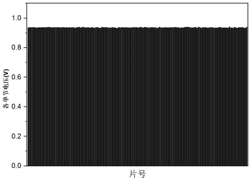
[0035] After the fuel cell stack is processed by the above method, the average voltage of the single chip is restored to about 0.94V, and the performance of the stack is improved by about 30-45%.

Embodiment 3

[0037] The oxidizing gas described in step (1) is pure oxygen or air, its working pressure is 80kPa, flow rate is 2*nslpm, n is the number of fuel cell stacks, n≥1, humidity is 100%, and the purge time is 30min.

[0038] The reducing gas described in step (2) is pure hydrogen, its working pressure is 80kPa, the flow rate is 1*n slpm, n is the number of fuel cell stacks, n≥1, the humidity is 100%, and the purge time is 30min .

[0039] Step (3) When the fuel cell stack is activated, the air in the cathode and the hydrogen in the anode adopt the stoichiometric mode, the stoichiometric ratio of the cathode is 2.5, and the stoichiometric ratio of the anode is 1.5.

[0040] All the other are with embodiment 1.

[0041] After the fuel cell stack is processed by the above method, the average voltage of the single chip is restored to about 0.96V, and the performance of the stack is improved by about 30-45%.

[0042] Using the above method, the cathode and anode of the fuel cell sta...


PUM


Abstract

The invention relates to a method for eliminating fuel cell coolant pollution, which comprises the following steps of (1) placing a fuel cell stack polluted by coolant on a test board, setting the working temperature of the fuel cell stack to be 50-65 DEG C, and simultaneously purging a cathode and an anode of a fuel cell by adopting a certain flow of humidified oxidizing gas, ane enabling the gas inlet direction of the purge gas to be opposite to the normal working direction of the fuel cell stack, (2) after the purging is finished, purging the cathode and the anode by adopting nitrogen, and simultaneously purging the cathode and the anode of the fuel cell stack by adopting a certain flow of humidified reducing gas, and (3) after the purging is finished, purging the cathode and the anode by adopting nitrogen, setting the temperature of the fuel cell stack to be 50-65 DEG C, introducing air into the cathode of the fuel cell stack, introducing hydrogen into the anode, switching on a load, and continuously increasing the current density of the fuel cell stack to finish pollution elimination and reactivation. Compared with the prior art, the method has the advantages of good elimination effect, low cost and the like.

Description

technical field [0001] The invention relates to a fuel cell, in particular to a method for eliminating the pollution of the fuel cell cooling fluid. Background technique [0002] As the core component of the fuel cell engine, the proton exchange membrane fuel cell maintains the capacity output process of the entire fuel cell system. Due to the high energy conversion efficiency of fuel cells, which breaks through the efficiency limitation of traditional internal combustion engines, fuel cell engines are becoming the most important development direction of power vehicle devices in the future. The membrane electrode (Membrane Electrode Assembly, MEA) and the bipolar plates on both sides constitute the basic unit of the fuel cell—a single cell. Several such single cells are combined into a fuel cell stack to meet different power outputs according to practical application needs. The most important part inside the fuel cell is the MEA, which can catalyze the conversion of chemica...

Claims


Application Information

Patent Timeline
Patent Type & Authority Applications(China)
IPC IPC(8): H01M8/04044H01M8/04223
CPCH01M8/04044H01M8/04223Y02E60/50
Inventor 朱从懿陈小晶陈广明甘全全戴威
Owner SHANGHAI SHENLI TECH CO LTD
Why Eureka
Try Eureka