Gas detonation driven ultra-high-speed launching system

A launch system, ultra-high-speed technology, used in aerodynamic tests, measurement of blasting force, instruments, etc., can solve problems such as limited gunpowder transportation and storage, uneven projectile acceleration, limited transportation and storage, etc., to achieve easy cleaning. and maintenance, high efficiency

Active Publication Date: 2021-06-04
INST OF MECHANICS - CHINESE ACAD OF SCI
View PDF11 Cites 12 Cited by
  • Summary
  • Abstract
  • Description
  • Claims
  • Application Information

AI Technical Summary

Problems solved by technology

[0003] Due to the high molecular mass and low sound velocity of ordinary propellant gas, even if a specially reinforced gun body is used, a large amount of propellant and very light projectiles are used, the maximum exit velocity of the primary propellant gas cannon can only reach about 3.6 km / s. So far, no gunpowder capable of producing low-molecular-weight gas has been found, so 3.6km / s can be said to be the limit speed of a first-class gunpowder gas gun
And because gunpowder also has shortcomings such as limited transportation and storage, toxic products, and pollution to the barrel wall, how to develop a detonation-driven two-stage light gas gun technology that uses hydrogen-oxygen detonation instead of gunpowder as the driving energy has important practical significance
[0004] In addition, traditional light gas guns use gunpowder as the driving energy, which has disadvantages such as large molecular mass of gunpowder, low sound velocity, toxic products, and limited transportation and storage. Moreover, when driven by traditional gunpowder, the acceleration of the projectile is relatively uniform, which can be regarded as Equal bottom pressure to accelerate the movement; while detonation-driven acceleration is mainly driven by shock waves back and forth, so the entire acceleration process of the projectile has multiple shock wave accelerations, and the acceleration of the projectile is uneven

Method used


Image

  • Gas detonation driven ultra-high-speed launching system
  • Gas detonation driven ultra-high-speed launching system
  • Gas detonation driven ultra-high-speed launching system

Examples


Embodiment 1

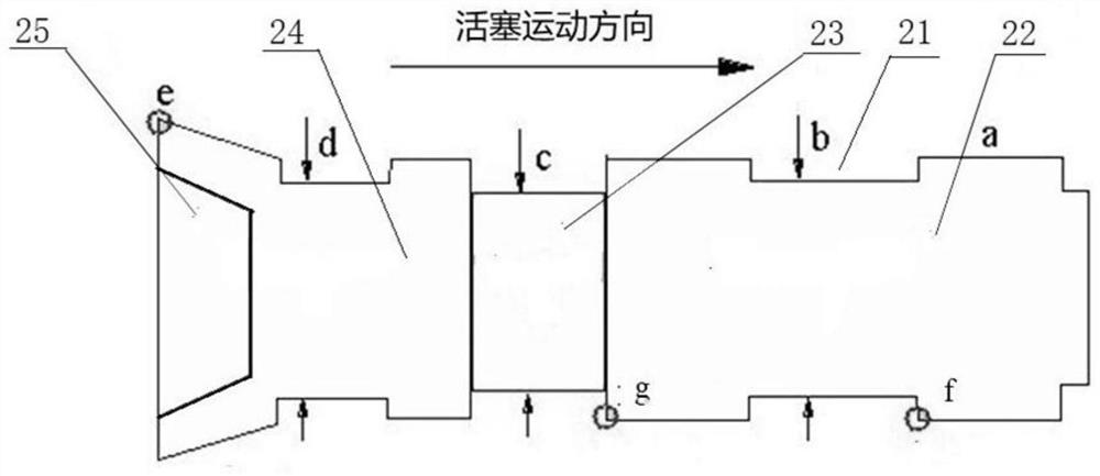
[0057] like figure 1 and figure 2 As shown, a gas detonation-driven ultra-high-speed launch system includes a hydrogen-oxygen charging system 1, a launch body, a test chamber 17, a buffer box 18 and a vacuum system,

[0058] The launching main body is set as a detonation secondary light gas cannon mechanism, and the first stage adopts a forward detonation method to control the shock wave to oscillate back and forth in the area between the wall surface of the left end of the detonation tube 4 and the rear wall surface of the piston 8, and the high pressure gas passes through the shock wave. Push the piston 8 to move, and after the second stage compresses the light gas through the high-speed motion of the piston 8 to reach the film breaking pressure, pushes the projectile 13 to move;

[0059] The launching main body is sequentially connected with a detonation tube 4, a compression tube 9, a film clipper 7, and a launch tube 14. The front end of the detonation tube 4 is provide...


PUM


Abstract

The invention belongs to the technical field of ultra-high-speed launching test experimental equipment, and discloses a gas detonation driven ultra-high-speed launching system in order to overcome the defects that gunpowder is large in molecular mass, the sound velocity is low, products are toxic, and transportation and storage are limited. A launching main body is sequentially connected with a detonation pipe, a compression pipe, a film clamping machine and a launching pipe; the launching main body is installed on a guide rail, and the guide rail is fixedly installed on a supporting frame; and the front end of the launching main body is connected with an oxyhydrogen inflation system through an ignition pipe, the rear end of the launching main body is connected with a test bin through a sealing device, the test bin is connected with a buffer box, and the buffer box is connected with a vacuum system. According to the gas detonation driven ultra-high-speed launching system, a detonation driven two-stage light gas gun technology adopting oxyhydrogen detonation as driving energy instead of the gunpowder is a low-cost and environment-friendly gas gun driving technology without needing initiating explosive devices, and higher efficiency and good launching repeatability are achieved.

Description

technical field [0001] The invention belongs to the technical field of ultra-high-speed launch testing experimental equipment, in particular to a gas detonation-driven ultra-high-speed launch system. Background technique [0002] A ballistic target is an experimental facility that launches a test model and projectile to a predetermined velocity, and can measure its aerodynamic characteristics or the impact and damage of the projectile on the target plate during the flight of the model. Ballistic targets first emerged in the 18th century to study the flight and lethality of bullets and artillery shells, and since World War II, ballistic targets have become a powerful tool for studying high-speed aircraft. With the development of the times, ballistic targets are widely used in the fields of ultra-high-speed aerodynamics and ultra-high-speed collision response, and at the same time promote the rapid development of ultra-high-speed re-entry vehicles, space debris protection stru...

Claims


Application Information

Patent Timeline
Patent Type & Authority Applications(China)
IPC IPC(8): F42B35/02G01M9/00G01N3/307G01L5/14
CPCF42B35/02G01M9/00G01N3/307G01L5/14Y02E60/32
Inventor 魏炳忱汪球赵伟张坤李进平
Owner INST OF MECHANICS - CHINESE ACAD OF SCI
Why Eureka
Try Eureka