Square wave and sine wave integrated control system for magnetic suspension permanent magnet motor

A permanent magnet motor and control system technology, applied in the control system, AC motor control, general control strategy, etc., can solve the problem of reducing the falling speed of the magnetic levitation motor, and achieve the effects of enhancing system reliability, easy debugging, and cost saving

Active Publication Date: 2021-06-04
BEIHANG UNIV
View PDF6 Cites 1 Cited by
  • Summary
  • Abstract
  • Description
  • Claims
  • Application Information

AI Technical Summary

Problems solved by technology

[0005] The technical problem of the present invention is: to overcome the deficiency of the existing single function control system, design a square wave and sine wave integrated control system for magnetic levitation permanent magnet motor, make full use of hardware resources, realize two kinds of The control method enhances the integration and flexibility of the control system; in order to make the structure of the control system more compact, a position sensorless method is used to detect the rotor position information required for square wave control and sine wave control to enhance the reliability of the control system; considering the magnetic Due to the particularity of the bearing, in this invention, the delayed power supply function based on the total power supply of the motor energy feedback is designed to reduce the drop speed of the magnetic levitation motor and protect the motor body

Method used


Image

  • Square wave and sine wave integrated control system for magnetic suspension permanent magnet motor
  • Square wave and sine wave integrated control system for magnetic suspension permanent magnet motor
  • Square wave and sine wave integrated control system for magnetic suspension permanent magnet motor

Examples


Embodiment Construction

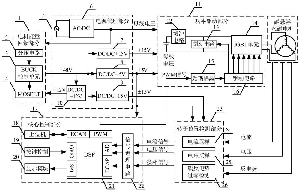
[0027] like figure 1 Shown is a block diagram of the system structure of the present invention, including a core control part 17 , a power drive part 11 , a rotor position detection part 23 , a motor energy feedback part 1 and a power management part 5 . The power management part 5 is responsible for providing strong and weak currents of the entire control system to ensure the normal operation of the system. The motor energy feedback part 1 is not only responsible for the supply of the weak power supply in the power management part during normal operation, but also undertakes the power-off protection function, that is, when the total power supply suddenly fails, the energy fed back to the bus by the motor is used to obtain the same energy as that during normal operation. Voltage, to output continuous voltage for the control system to avoid the accident that the magnetic suspension bearing falls at high speed due to sudden power failure. The rotor position detection part 23 is...


PUM


Abstract

The invention relates to a square wave and sine wave integrated control system for a magnetic suspension permanent magnet motor. The square wave and sine wave integrated control system comprises a core control part, a power driving part, a rotor position detection part, a motor energy feedback part and a power supply management part; the core control part comprises a DSP control unit, a signal input/output interface and a communication interface; the power driving part comprises an IGBT unit and a driving circuit, the rotor position detection part comprises a line counter electromotive force zero crossing point detection circuit and a voltage and current sampling circuit, the motor energy feedback part comprises a Buck control unit with wide voltage range input, and the power supply management part comprises an alternating current-to-direct current rectifier module and a direct current-to-direct current power supply isolation module. According to the invention, two functions of square wave control and sine wave control are realized in the same hardware system, the integrated design is compact in structure, and the integration level of the motor control system is improved; functions are comprehensive, and reliability can be enhanced; the system is easy to debug and flexible to implement, and effectively widens the application range of a single-function motor control system.

Description

technical field [0001] The invention relates to a square wave and sine wave integrated control system for a magnetic levitation permanent magnet motor, which realizes the square wave and sine wave integrated control in one system, and is suitable for rotating machinery related to magnetic levitation motor technology such as a magnetic levitation molecular pump and a magnetic levitation flywheel. , It is also suitable for industrial fields related to motor drives such as servo drives, blowers, and electric spindles. Background technique [0002] Compared with traditional motors (such as DC motors, AC synchronous motors, switched reluctance motors and asynchronous induction motors, etc.), permanent magnet motors have compact structure, high energy density, high operating efficiency, and good control characteristics. Excitation, and can be directly connected with high-speed rotating loads. Compared with mechanical bearings, magnetic suspension bearings are becoming more and mo...

Claims


Application Information

Patent Timeline
Patent Type & Authority Applications(China)
IPC IPC(8): H02P23/00H02P23/14H02P25/02H02N15/00H02J9/06
CPCH02P23/0004H02P23/14H02P25/02H02N15/00H02J9/061
Inventor 陈宝栋毛琨郭傲张旨杨伟伟郑世强
Owner BEIHANG UNIV
Why Eureka
Try Eureka