
Self-condensation type compressed carbon dioxide energy storage system and method based on vortex tube

A high-pressure carbon dioxide and carbon dioxide technology, used in compressors, refrigeration and liquefaction, refrigerators, etc., can solve the problems of requiring additional cold sources, difficult to liquefy, etc., to achieve the effect of reducing system volume, low cost, and stable power output

Active Publication Date: 2021-06-08
XI AN JIAOTONG UNIV
View PDF6 Cites 6 Cited by
  • Summary
  • Abstract
  • Description
  • Claims
  • Application Information

AI Technical Summary

Problems solved by technology

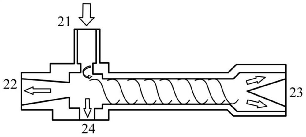
[0006] The purpose of the present invention is to provide a self-condensing compressed carbon dioxide energy storage system and method based on vortex tubes to solve the problem that the liquefaction of expanded carbon dioxide in the current compressed carbon dioxide energy storage technology requires an additional cold source, and it is difficult to liquefy at room temperature Vortex tubes are generally used in refrigeration systems. Gas under pressure expands and accelerates through the vortex tubes, forms a free vortex, and then separates to obtain the cold air flow required for refrigeration.

Method used


Image

  • Self-condensation type compressed carbon dioxide energy storage system and method based on vortex tube
  • Self-condensation type compressed carbon dioxide energy storage system and method based on vortex tube

Examples


Embodiment Construction

[0028] The present invention is described in further detail below:

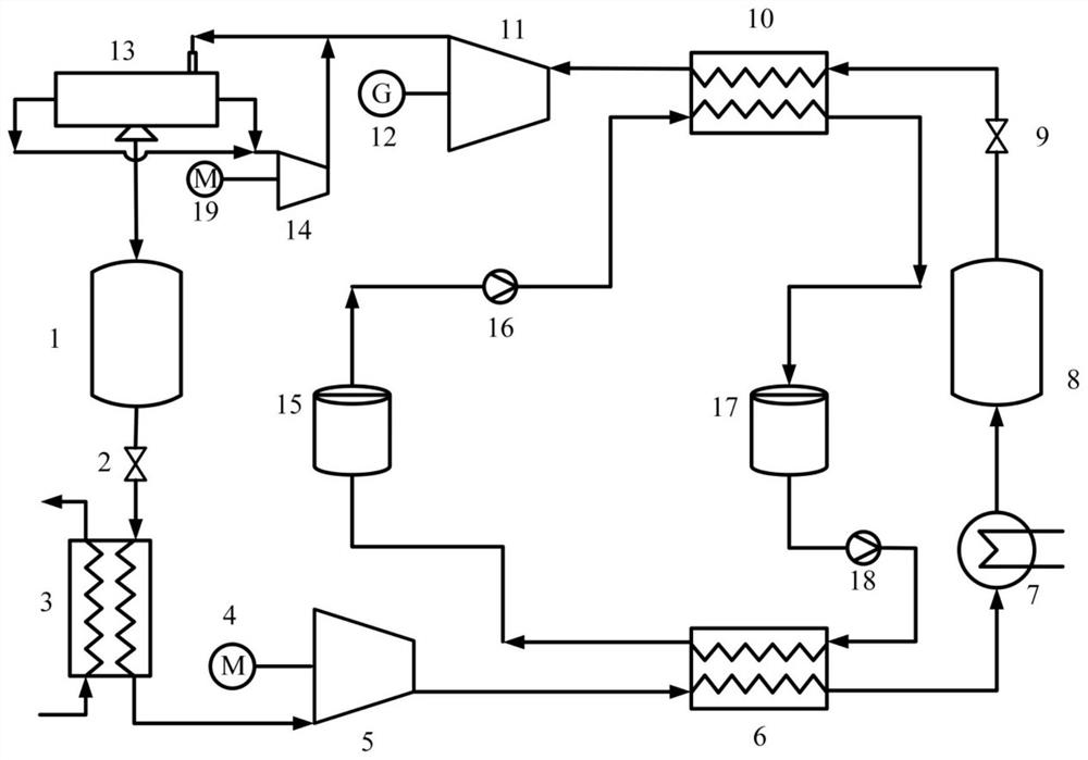
[0029]A self-condensing compressed carbon dioxide energy storage system based on vortex tubes can effectively stabilize the power fluctuations of renewable energy, improve the utilization rate of renewable energy, and also realize peak-shaving and valley-filling of power systems and reduce peak-valley differences. The invention takes electric energy as input and uses carbon dioxide as energy storage working medium. The electric energy is converted into the pressure potential energy and internal energy of the carbon dioxide working fluid through the compressor for storage, and the stored energy is released stably and controllably through the turbine. The main advantage is that both high-pressure and low-pressure carbon dioxide are stored in liquid form, and artificial storage tanks can meet the demand; the vortex tube is used to realize the self-condensation of low-pressure carbon dioxide after turbo expansion...


PUM


Abstract

The invention discloses a self-condensation type compressed carbon dioxide energy storage system and method based on a vortex tube. The self-condensation type compressed carbon dioxide energy storage system and method based on the vortex tube aim to solve the problems that in the existing compressed carbon dioxide energy storage technology, low-pressure carbon dioxide liquefaction depends on a low-temperature cold source, and liquefaction is difficult to carry out under the room temperature condition. The self-condensation type compressed carbon dioxide energy storage system is mainly composed of a carbon dioxide energy storage circulation loop and a heat storage circulation loop. A low-pressure carbon dioxide energy storage working medium is liquefied under the room temperature condition through the vortex tube. The compressed carbon dioxide energy storage system can be used for stabilizing power fluctuation of renewable energy sources, improving the grid-connected capacity grade of the renewable energy sources, and can also be used for peak clipping and valley filling of an electric power system, and the peak-valley difference is reduced. The self-condensation type compressed carbon dioxide energy storage system and method based on the vortex tube have important practical significance and engineering application value in the aspects of reducing carbon emission, promoting economic development, accelerating energy structure transformation of China and the like.

Description

technical field [0001] The invention belongs to the technical field of physical energy storage, and in particular relates to a self-condensing compressed carbon dioxide energy storage system and method based on a vortex tube. Background technique [0002] Energy is the material basis of social development, but also a key factor restricting economic development. With the continuous development of economy and society, energy consumption continues to increase, and continuing to increase traditional power production capacity will bring severe environmental pollution problems. The development and utilization of renewable energy such as solar energy and wind energy provide a way to solve the current energy and environmental problems in our country. However, wind energy and solar energy have the characteristics of volatility and intermittency. The power fluctuation brought about by large-scale grid connection is the main difficulty for their large-scale and effective utilization, ...

Claims


Application Information

Patent Timeline
IPC IPC(8): F25B9/00F25B9/04F28D20/00F01D15/10F01K25/04
CPCF01D15/10F01K25/04F25B9/008F25B9/04F28D20/0034Y02E60/14Y02E70/30
Inventor 赵攀许文盼苟非非王江峰戴义平
Owner XI AN JIAOTONG UNIV
Learn More