Device and method for estimating blood vessel blood flow velocity field through transcranial ultrasound

A blood flow velocity and blood vessel technology, applied in blood flow measurement devices, ultrasonic/sonic/infrasonic diagnosis, ultrasonic/sonic/infrasonic image/data processing, etc., can solve attenuation, insufficient frame rate, and inability to estimate blood flow velocity Distribution and other issues to achieve the effect of improving frame rate and high accuracy

Active Publication Date: 2021-06-11
XI AN JIAOTONG UNIV
View PDF5 Cites 5 Cited by
  • Summary
  • Abstract
  • Description
  • Claims
  • Application Information

AI Technical Summary

Problems solved by technology

However, transcranial ultrasound imaging is blocked by the skull. Although the signal can be enhanced by releasing contrast microbubbles in blood vessels, due to the half-wavelength limitation and the influence of sound wave attenuation after cranial penetration, it is impossible to obtain high-resolution ultrasound images and effectively distinguish blood vessels. Therefore, it is not suitable for estimating the blood flow velocity field of small cerebral blood vessels such as transcranial submillimeter vessels (vessels with a diameter of 0.1 to 1 mm) and microvessels (vessels with a diameter of less than 0.1 mm).
In addition, the traditional ultrasonic imaging scanning method is line scanning, that is, the ultrasonic transducer transmits signals one by one according to the arrangement of the array elements and receives echo signals one by one. This scanning method will cause the signals received by the array elements to be not at the same time. The problem of insu...

Method used


Image

  • Device and method for estimating blood vessel blood flow velocity field through transcranial ultrasound
  • Device and method for estimating blood vessel blood flow velocity field through transcranial ultrasound
  • Device and method for estimating blood vessel blood flow velocity field through transcranial ultrasound

Examples


Embodiment Construction

[0038] The present invention will be described in further detail below in conjunction with the accompanying drawings and embodiments. The examples are only used to explain the present invention, not to limit the protection scope of the present invention.

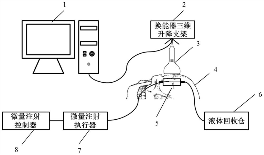
[0039] see figure 1 , the transcranial ultrasonic small vessel blood velocity field testing device proposed by the present invention mainly includes a microinjection pump (the microinjection pump is composed of a microinjection controller 8 and a microinjection actuator 7, and the microinjection actuator 7 is controlled by a microinjection The execution unit of the controller 8 and the syringe installed on the execution unit consist of), a low-frequency ultrasonic transducer 3 , a three-dimensional lifting bracket 2 of the transducer and a programmable ultrasonic platform 1 . The programmable ultrasound platform 1 and the computer form an integral body, which is the basic equipment for collecting and processing ultrasound ech...


PUM

PropertyMeasurementUnit
Diameteraaaaaaaaaa

Abstract

The invention discloses a device and a method for estimating a blood flow velocity field of a blood vessel through transcranial ultrasound. The device mainly comprises a low-frequency ultrasonic transducer, a programmable ultrasonic platform and a computer. The method is characterized in that the low-frequency ultrasonic transducer is used for transmitting a plane wave attached with a linear frequency modulation signal for imaging; space-time filtering on the radio frequency data, positioning and tracking radiography microbubbles are performed to obtain a blood vessel structure diagram, and the diameter and position coordinates of the blood vessel are confirmed; and a traditional image cross-correlation algorithm and a fast Fourier transform algorithm are combined and applied to speed distribution estimation. The method can effectively overcome the weakening of the echo signal intensity caused by transcranial ultrasonic attenuation, can accurately determine the blood vessel position area under the condition that the imaging resolution of the low-frequency ultrasonic transducer is low, and is particularly suitable for estimating the blood flow velocity distribution of the transcranial ultrasonic small blood vessel.

Description

technical field [0001] The invention belongs to the technical field of acoustic measurement, and relates to a device for estimating a vascular blood flow velocity field by using ultrasonic imaging and a corresponding blood flow velocity field estimation method. Background technique [0002] Cerebral small vessel disease has great damage to human body, cognition and spirit. Therefore, it is necessary to understand and master the parameters reflecting the physiological and pathological changes of cerebral small vessel disease in the basic research and diagnosis and treatment of cerebral small vessel disease. and data. Vascular blood flow velocity field refers to the spatial distribution of blood flow velocity on the radial section of the vessel. In fluid mechanics, the vessel lumen is approximated to a circular tube, and the flow of blood in the vessel conforms to the laminar flow in the circular tube. The vascular blood flow velocity field It presents a parabolic shape, and ...

Claims


Application Information

Patent Timeline
IPC IPC(8): A61B8/06
CPCA61B8/06A61B8/52A61B8/5215A61B8/5207
Inventor 万明习梁美玲杨雅博刘嘉程
Owner XI AN JIAOTONG UNIV
Why Eureka
Try Eureka