Wet desulphurization and dust removal equipment for industrial waste gas and use method thereof

A technology for wet desulfurization and dust removal equipment, applied in separation methods, chemical instruments and methods, combined devices, etc., can solve the problems of inability to meet emission standards, inability to perform a large amount of fog removal, and poor desulfurization effect, and increase the contact time. , the effect of increasing the contact area and improving the processing efficiency

Inactive Publication Date: 2021-06-11
LIAONING INST OF SCI & TECH
View PDF7 Cites 7 Cited by
  • Summary
  • Abstract
  • Description
  • Claims
  • Application Information

AI Technical Summary

Problems solved by technology

In the existing equipment, limestone water is used to desulfurize the gas. In the desulfurization process, generally only one layer of spray is installed, and the gas can only be in conta

Method used


Image

  • Wet desulphurization and dust removal equipment for industrial waste gas and use method thereof
  • Wet desulphurization and dust removal equipment for industrial waste gas and use method thereof
  • Wet desulphurization and dust removal equipment for industrial waste gas and use method thereof

Examples


Embodiment 1

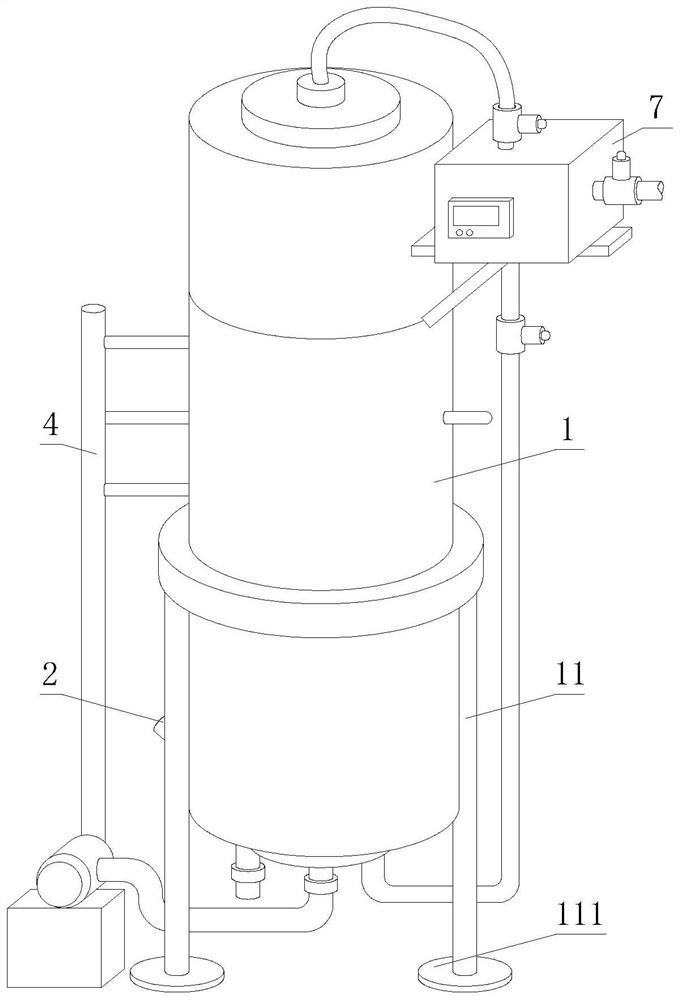
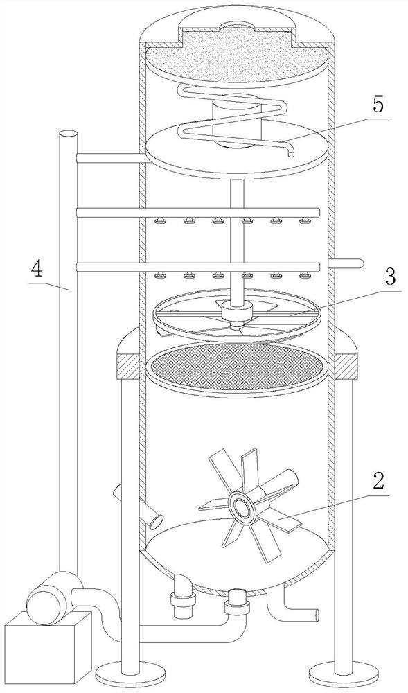
[0041] see Figure 1-Figure 2 , an industrial waste gas wet desulfurization and dust removal equipment and its use method, comprising an outer cylinder body 1, a bracket 11 is fixedly installed under the outer side of the outer cylinder body 1, a foot 111 is fixed under the bracket 11, and the interior of the outer cylinder body 1 is arranged The primary desulfurization device 2, the secondary desulfurization device 3 is installed in the outer cylinder 1 above the primary desulfurization device 2, the side end of the secondary desulfurization device 3 is provided with a spray device 4, and the top of the outer cylinder 1 is provided with a dehydration device 5, the dehydration device The 5 side end is connected with the detection device 6 .

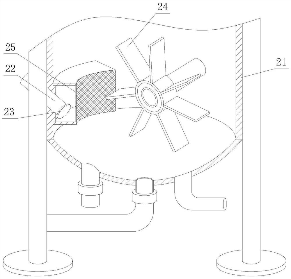
[0042] see image 3 , the preliminary desulfurization device 2 comprises a water tank 21, an air inlet pipe 22, an anti-backflow device 23, a stirring blade 24 and a dispersion net 25, and the stirring blade 24 is arranged in the water t...

Embodiment 2

[0053] see Figure 11 , an industrial waste gas wet desulfurization and dust removal equipment and its use method, comprising an outer cylinder body 1, a bracket 11 is fixedly installed under the outer side of the outer cylinder body 1, a foot 111 is fixed under the bracket 11, and the interior of the outer cylinder body 1 is arranged The primary desulfurization device 2, the secondary desulfurization device 3 is installed in the outer cylinder 1 above the primary desulfurization device 2, the side end of the secondary desulfurization device 3 is provided with a spray device 4, and the top of the outer cylinder 1 is provided with a dehydration device 5, the dehydration device 5. The side end is connected with the detection device 6. The preliminary desulfurization device 2 includes a water tank 21, an air intake pipe 22, an anti-backflow device 23, a stirring blade 24, and a dispersion net 25. The water tank 21 is provided with a stirring blade 24, and the side end of the water...


PUM


Abstract

The invention discloses wet desulphurization and dust removal equipment for industrial waste gas and a use method thereof, and belongs to the technical field of industrial waste gas desulfurization. The equipment includes an outer cylinder, wherein a support is fixedly mounted below the outer side of the outer cylinder, and supporting legs are fixed below the support. According to the equipment and the use method thereof, the contact area with limestone water is increased, the reaction efficiency is improved, internal water backflow is prevented, the situation that gas rises too fast and cannot make contact with a spraying device is prevented, the contact time is prolonged, the treatment efficiency is improved, and the limestone water sprayed out of a spray head makes full contact with the gas, thus improving the desulphurization effect, forming a wet desulphurization cycle, increasing the utilization efficiency, reducing the waste of resources, preventing condensate water residues inside, avoiding secondary pollution caused by long-time residues, improving the condensation conveying efficiency, strictly controlling the gas emission quality, protecting the environment from being polluted, improving the desulphurization quality, reducing the waste of heat energy and increasing the treatment benefits.

Description

technical field [0001] The invention relates to the technical field of industrial waste gas desulfurization, in particular to a wet desulfurization and dust removal equipment for industrial waste gas and a use method thereof. Background technique [0002] Industrial waste gas refers to the general term for all kinds of pollutant gases that are discharged into the air during fuel combustion and production processes in the factory area. These exhaust gases include: carbon dioxide, carbon disulfide, hydrogen sulfide, fluoride, nitrogen oxides, chlorine, hydrogen chloride, carbon monoxide, sulfuric acid (mist) lead mercury, beryllium compounds, smoke and productive dust, which will pollute the air when discharged into the atmosphere. These substances enter the human body through the respiratory tract in different ways, some directly cause harm, and some have a cumulative effect, which will seriously endanger human health. Different substances will have different effects. Wet el...

Claims


Application Information

Patent Timeline
IPC IPC(8): B01D53/50B01D50/00B01D53/78
CPCB01D53/504B01D53/502B01D50/00B01D2251/404B01D2251/604
Inventor 吴丽红
Owner LIAONING INST OF SCI & TECH
Why Eureka
Try Eureka