Waste gas treatment device used for catalytic combustion

An exhaust gas treatment device and catalytic combustion technology, applied in combustion methods, combustion types, incinerators, etc., can solve the problems of uneven mixing of exhaust gas and catalyst, affecting the efficiency of catalytic work, etc., to reduce mixing time, improve practicability, The effect of improving quality

Active Publication Date: 2021-06-15
山西鸿泰来科技有限公司
View PDF12 Cites 2 Cited by
  • Summary
  • Abstract
  • Description
  • Claims
  • Application Information

AI Technical Summary

Problems solved by technology

[0006] The technical problem to be solved in the present invention is to provide an exhaust gas treatment device for catalytic combustion, one of the purposes is to have the function of facilitating the uniform mixing of exhaust gas and catalyst, and to solve the problem that traditional exhaust gas treatment devices for catalytic combustion are easy to use. The mixing of the exhaust gas and the catalyst is uneven, which leads to the problem of affecting the efficiency of the catalytic work; another purpose is to solve the problem that the exhaust gas of the traditional exhaust gas treatment device for catalytic combustion is often mixed with fine solid impurities, so as to improve The effect of the quality of the catalytic product

Method used


Image

  • Waste gas treatment device used for catalytic combustion
  • Waste gas treatment device used for catalytic combustion
  • Waste gas treatment device used for catalytic combustion

Examples


Embodiment 1

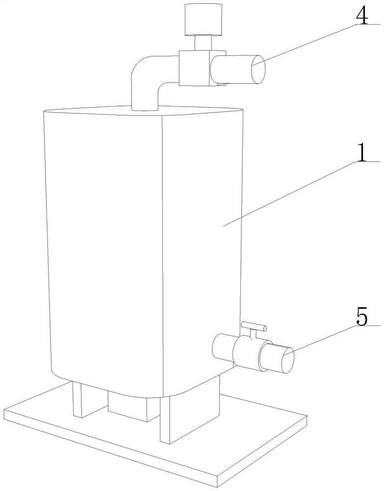
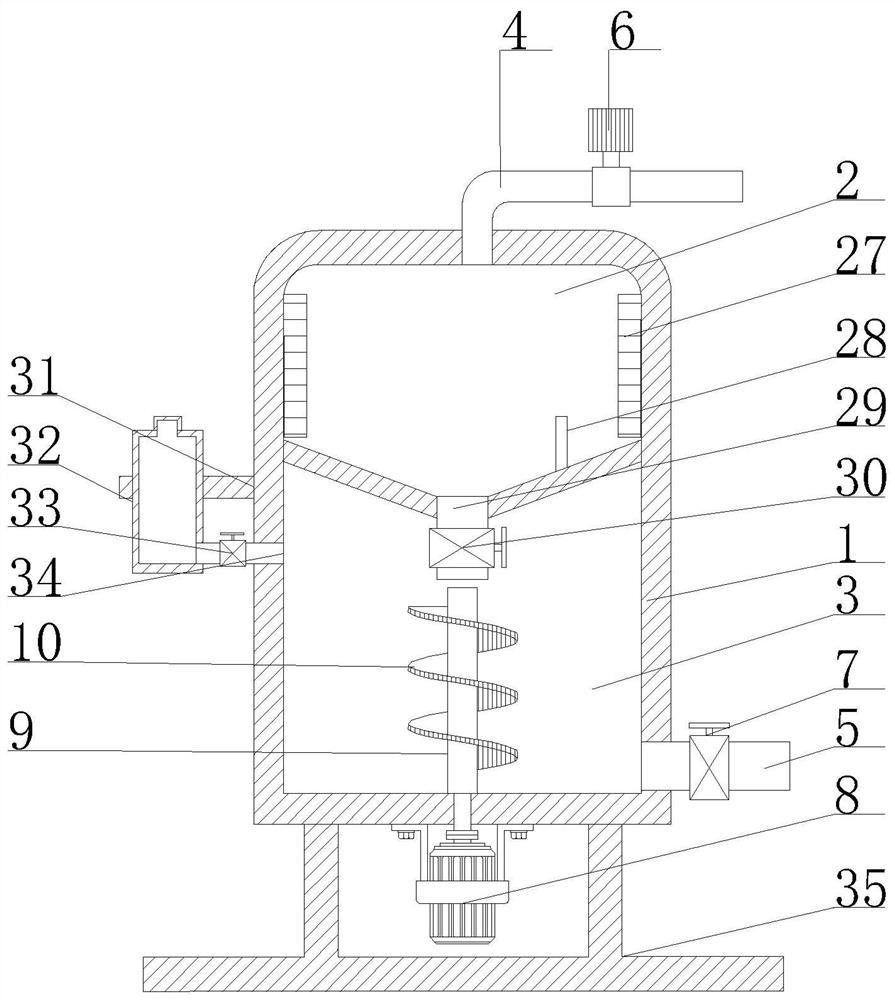
[0034] Such as figure 1 - figure 2 As shown, the present invention provides an exhaust gas treatment device for catalytic combustion, including a treatment mechanism 1, a heating chamber 2, a catalytic chamber 3, an air inlet pipe 4, an air outlet pipe 5, a negative pressure pump 6, and a first valve 7 , a drive motor 8, a rotating roller 9 and a spiral blade 10, a heating chamber 2 and a catalytic chamber 3 are provided inside the processing mechanism 1, the heating chamber 2 is located above the catalytic chamber 3, and the top of the processing mechanism 1 is provided with an inlet Trachea 4, negative pressure pump 6 is arranged on the surface of air inlet pipe 4, outlet pipe 5 is arranged on the bottom right side of processing mechanism 1, first valve 7 is arranged on the surface of outlet pipe 5, and drive motor 8 is arranged on the bottom of processing mechanism 1 , the output end of the driving motor 8 is provided with a rotating roller 9 , the rotating roller 9 penet...

Embodiment 2

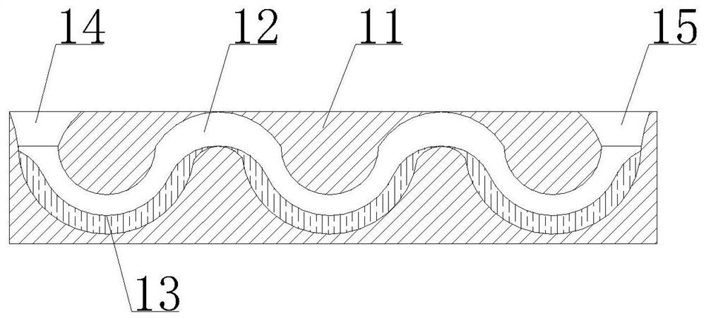
[0037] Such as Figure 3-7 Shown, on the basis of embodiment 1, the present invention provides a kind of technical scheme: helical blade 10 comprises blade body 11 and flow groove 12, and the top surface of blade body 11 is provided with feed inlet 14, and the bottom surface of blade body 11 There is a discharge port 15, the feed port 14 and the discharge port 15 are connected through the set flow tank 12, the bottom of the inner wall of the flow tank 12 is provided with a filter mechanism 13, and the surface of the filter mechanism 13 is provided with a filter tank 16, the filter tank The bottom of the inner wall of 16 is provided with a viscous filter layer 17 to the left, and the bottom of the filter tank 16 is provided with an arc-shaped groove 18 to the left. The viscous filter layer 17 includes a viscous adsorption layer 22 and an adhesive bristle 23. The inner wall of the groove 16 is fixedly connected, the top of the viscous adsorption layer 22 is uniformly provided wi...

Embodiment 3

[0039] Such as Figure 1-2 As shown, on the basis of Embodiment 1 and Embodiment 2, the present invention provides a technical solution: preferably, the inner wall side of the heating chamber 2 is provided with a heater 27, and the inner wall bottom of the heating chamber 2 is provided with a temperature sensor device 28, the bottom of the heating chamber 2 communicates with the catalytic chamber 3 through the flow pipe 29 provided, the surface of the flow pipe 29 is provided with a solenoid valve 30, the temperature sensing device 28 is connected with the signal of the solenoid valve 30, and the left side of the processing mechanism 1 The side is movably connected with a catalyst storage bottle 32 through a fixed bracket 31 provided, and the bottom of the catalyst storage bottle 32 is provided with a feeding pipe 33, and the feeding pipe 33 runs through the processing mechanism 1 and extends inside the catalytic chamber 3, and the feeding pipe 33 A second valve 34 is provided...


PUM


Abstract

The invention discloses a waste gas treatment device used for catalytic combustion, and relates to the technical field of waste gas treatment. The waste gas treatment device comprises a treatment mechanism, a heating chamber, a catalytic chamber, a gas inlet pipe, a gas outlet pipe, a negative pressure pump, a first valve, a driving motor, a rotating roller and a spiral blade. The heating chamber and the catalytic chamber are formed in the treatment mechanism, the heating chamber is located above the catalytic chamber, the gas inlet pipe is arranged at the top of the treatment mechanism, the negative pressure pump is arranged on the surface of the gas inlet pipe, the gas outlet pipe is arranged at the bottom of the right side of the treatment mechanism, and the first valve is arranged on the surface of the gas outlet pipe. According to the device, a catalyst and waste gas can be fully mixed, the mixing time of the catalyst and the waste gas can be shortened, the waste gas can be more comprehensively catalyzed, fine solid impurities in the gas can be filtered, meanwhile, the quality of a catalytic product is improved, the filtering function is enhanced, and the practicability of a filtering mechanism in the waste gas treatment device used for catalytic combustion is improved.

Description

technical field [0001] The invention relates to the technical field of exhaust gas treatment, in particular to an exhaust gas treatment device for catalytic combustion. Background technique [0002] The catalytic combustion of waste gas refers to the rapid oxidation of hydrocarbons in organic waste gas into water and carbon dioxide under the condition of low temperature under the action of oxygen to achieve the purpose of treatment. The catalytic combustion method to treat industrial organic waste gas is a technology that appeared in the late 1940s. Since the United States developed the world's first catalytic combustion device in 1949, this technology has been widely used in paint, rubber processing, plastic processing, Resin processing, leather processing, food industry and foundry industry, and also used in automobile exhaust gas purification. In 1973, China began to use the catalytic combustion method to treat the organic waste gas discharged from the enameled wire dryi...

Claims


Application Information

Patent Timeline
Patent Type & Authority Applications(China)
IPC IPC(8): F23G7/07F23G5/50B01D49/00F23G5/44
CPCF23G7/07F23G5/44F23G5/50B01D49/00F23G2201/60Y02A50/20
Inventor 田华友
Owner 山西鸿泰来科技有限公司
Why Eureka
Try Eureka