
A high-efficiency vertical hydrodynamic turbulent mill for superhard and ultrafine powder

An ultra-fine powder and super-hard technology, which is applied in grain processing and other directions, can solve the problems of reducing the fineness of crushing, cumbersome operation, and particle powder agglomeration, so as to reduce the dynamic load and static load, increase the collision probability, and strengthen the impact energy effect

Active Publication Date: 2022-07-22
NANJING INST OF TECH
View PDF7 Cites 0 Cited by
  • Summary
  • Abstract
  • Description
  • Claims
  • Application Information

AI Technical Summary

Problems solved by technology

Limited by the principle, these traditional equipment still have certain technical difficulties in order to achieve the industrial production of ultra-hard and ultra-fine materials, and there are generally problems such as low output and high energy consumption, especially in the ultra-fine state where particle powder agglomeration and inconsistency The technical bottleneck of refinement, especially for superhard powder
[0003] The Chinese patent "Highly Turbulent Mill and Its Dual Negative Pressure Turbine" with application number 200580008197.2 uses the double negative pressure turbine to rotate at high speed in the grinding cavity driven by the electric shaft, and high-intensity eddy currents and turbulent flows will be generated inside the grinding cavity, thereby forming Gas-solid two-phase flow, under the action of high turbulence, the materials will undergo strong self-grinding with each other, and at the same time generate strong collision and shearing forces, thereby crushing the materials, but there are several technical drawbacks in this device: First, the The device does not consider adding grinding media with a large particle size difference to grind the materials between the grinding media. Instead, it uses the small particle size difference of its own materials to grind each other, which cannot produce very effective impact collision and vibration crushing effects. Furthermore, gas-solid Grinding is prone to agglomeration and reverse crushing of ultrafine powder, which is not conducive to reducing the fineness of grinding, and leads to increased energy consumption and reduced efficiency; secondly, the structure of the device is too complicated, which makes the operation cumbersome and high in cost; furthermore, the device The use of multiple motors increases the failure rate of the entire device, and the noise of the motors is large, so it is difficult to achieve mass-produced ultrafine pulverization products

Method used


Image

  • A high-efficiency vertical hydrodynamic turbulent mill for superhard and ultrafine powder
  • A high-efficiency vertical hydrodynamic turbulent mill for superhard and ultrafine powder
  • A high-efficiency vertical hydrodynamic turbulent mill for superhard and ultrafine powder

Examples


Embodiment 1

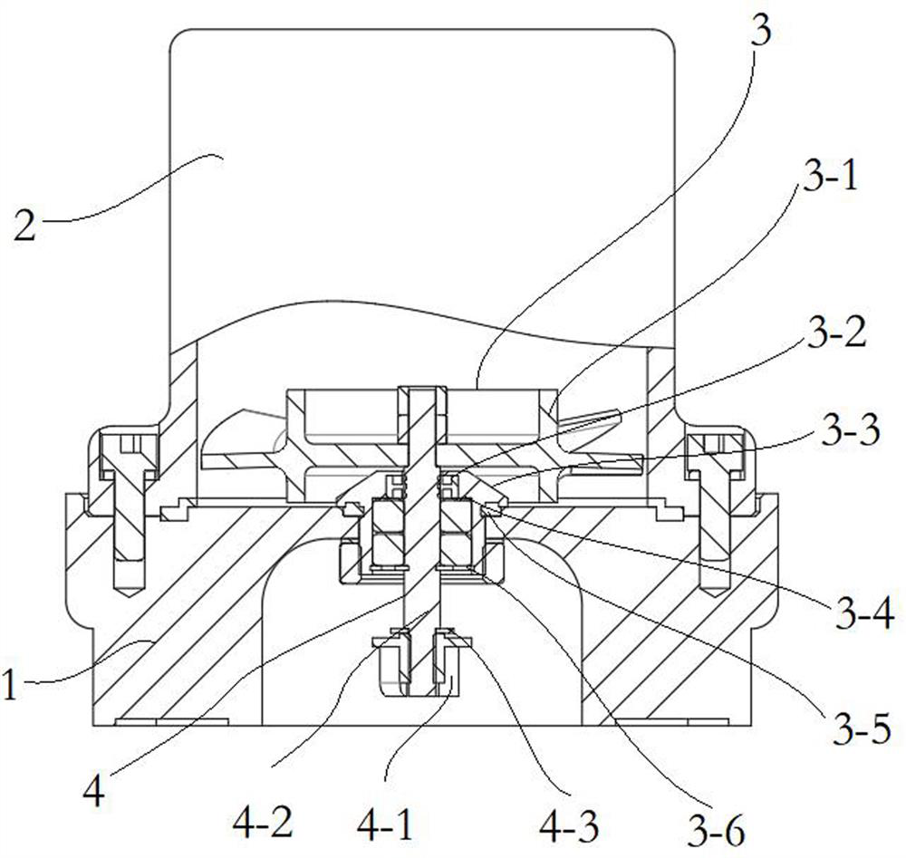
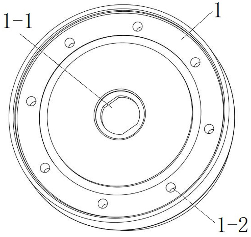
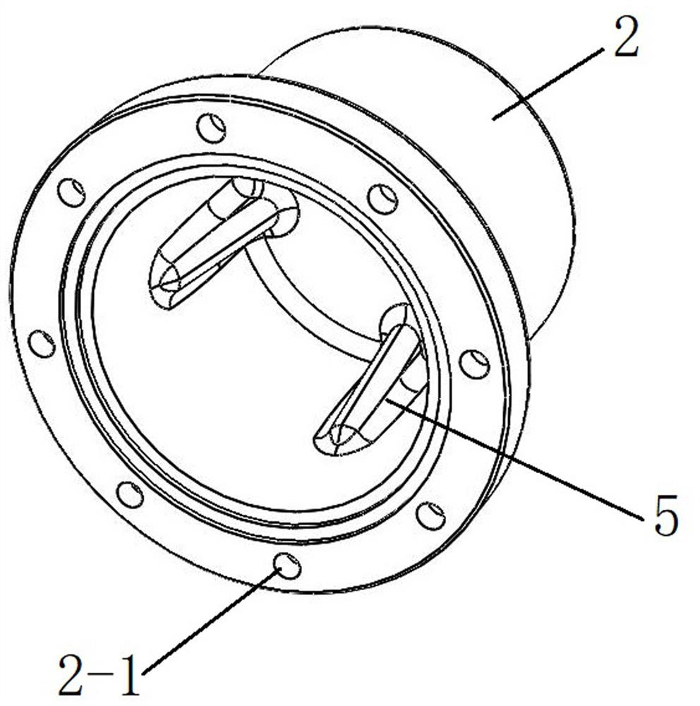
[0034] like Figures 1 to 3 As shown, a super-hard and ultra-fine powder vertical hydraulic turbulent mill of the present invention includes a mechanism base 1, a cover cylinder 2, a space curved turbine grinding mechanism 3 and a main shaft drive mechanism 4. The middle of the mechanism base 1 is provided with Mounting hole 1-1, and the bottom of the mechanism base 1 corresponding to the mounting hole 1-1 is provided with a spindle drive mechanism accommodating cavity, and the top of the mechanism base 1 around the mounting hole 1-1 is evenly distributed with 8 lower threaded holes 1-2. There are 8 upper threaded holes 2-1 on the outer edge of the bottom of the cylinder 2, the cover cylinder 2 is covered on the mechanism base 1, and a sealing washer is added between the cover cylinder 2 and the mechanism base 1, and the upper threaded holes 2- 1 is aligned with the lower threaded holes 1-2, and the upper and lower threaded holes are threaded through bolts. The cover cylinder ...

Embodiment 2

[0041] A super-hard and ultra-fine powder vertical hydraulic turbulent mill, the difference between this embodiment and Embodiment 1 is that the inner blades of the space curved turbine 3-1 and the axial disk are at an inclination angle of 30°; The inner wall is provided with four spoiler ribs 5, and the four spoiler ribs 5 are vertically and evenly distributed on the top of the inner wall of the cover cylinder 2 at an interval of 90° (such as Figure 7 shown).

[0042] The turbulent viscosity simulation test is carried out by using the superhard and ultrafine powder vertical hydraulic turbulent mill of the present embodiment, and the results are as follows: Figure 9 As shown, it can be seen that the turbulent viscosity in the center of the space curved turbine 3-1 is higher, and the two sides above the space curved turbine 3-1 are higher than the upper center, and the overall distribution of the turbulent viscosity inside the cover cylinder 2 is uneven. Turbulence is due to...


PUM


Abstract

The invention discloses a high-efficiency super-hard and ultra-fine powder vertical hydraulic turbulent mill. A cover cylinder is detachably mounted on a mechanism base, the inner cavity of the cover cylinder and the mechanism base enclose a grinding inner cavity, and the inner wall of the top of the cover cylinder is provided with There are spoiler ribs, the main shaft drive mechanism is installed on the mechanism base, and drives and connects the space curved turbine grinding mechanism to drive the space curved turbine grinding mechanism to rotate synchronously. The space curved turbine grinding mechanism is installed in the grinding cavity. The invention has the advantages of simple structure, small volume, low cost, and reduces the dynamic load and static load of the grinding equipment. The space curved turbine is used to generate a liquid-solid turbulent flow field under high-speed rotation, and the particles generate strong turbulent kinetic energy in the turbulent flow field, which can avoid the bottom of the cylinder. The energy-depleted area strengthens the impact energy between the grinding medium and the material; the spoiler rib can disturb the eddy current field in the cylinder during the grinding process, greatly improving the collision probability between the grinding medium and the material, so as to achieve ultra-micronization through particle collision, shearing and friction. , the obtained powder has high purity and fine particle size.

Description

technical field [0001] The invention belongs to the technical field of grinding equipment, and in particular relates to an efficient superhard and ultrafine powder vertical hydraulic turbulent mill. Background technique [0002] Since the beginning of this century, with the rapid development of industry, the demand for ultra-fine and ultra-fine powder is extremely fast, and its manufacturing industry has developed rapidly. At present, the equipment for mechanically preparing ultrafine and ultrafine powder materials mainly includes drum ball mills, vibration mills, planetary ball mills, sand mills and jet mills. Limited by the principle, these traditional equipment still have certain technical difficulties in order to achieve the industrial production of superhard and ultrafine materials, and there are generally problems of low output and high energy consumption, especially in the ultrafine state, there are particle powder agglomeration and inconsistency. The technical bottl...

Claims


Application Information

Patent Timeline
Patent Type & Authority Patents(China)
IPC IPC(8): B02C19/00B02C23/00
CPCB02C19/005B02C23/00
Inventor 杨小兰刘极峰叶文旭孙凯郑轩宇王晟
Owner NANJING INST OF TECH
Learn More